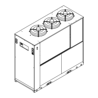
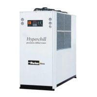
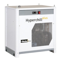
This document describes the Hyperchill (50Hz) series of water chillers, specifically models ICE076, ICE090, and ICE116, manufactured by Parker Hannifin Manufacturing S.r.l. These are monoblock units designed for producing chilled water in a closed circuit, suitable for professional use.
Function Description
The Hyperchill units are water coolers that produce chilled water for various industrial applications. They operate on a closed-circuit system, ensuring efficient and controlled cooling. The compressor, pump, and fan motors are equipped with thermal protection to prevent overheating. The chillers can be configured for air-cooled (axial or centrifugal fans) or water-cooled operation, depending on the specific model and installation requirements. They feature a control panel for setting desired temperatures, monitoring operational parameters, and managing alarms. Remote ON/OFF control is an available feature, allowing for flexible operation.
Important Technical Specifications
The document provides detailed technical specifications for the ICE076, ICE090, and ICE116 models.
- Refrigerant: R407C (HFC), classified under SAFETY GROUP A1 - EN378 (group 2 fluid according to PED 2014/68/EU). The Global Warming Potential (GWP) is 1774.
- Power Supply: 400V±10%/3ph/50Hz (4-wire cable: 3 phase conductors + earth, no neutral). The voltage tolerance is +/- 10% for voltage and +/- 1% for frequency. Maximum permissible voltage imbalance is 2%. Max grid impedance value is 0.274 ohm.
- Temperature Control: Set point range is adjustable, with a default differential of 4.0. Lower set point limit is 5.0.
- Water Characteristics:
- Temperature: ≥50°F (10°C)
- ΔT IN/OUT: 5-15°C
- Max % Glycol: 50%
- Pressure: 43.5-145 PSIg (3-10 barg)
- pH: 7.5-9
- Electrical Conductivity: 10-500 μS/cm
- Langelier Saturation Index: 0-1
- Chloride (CL-): <50 ppm
- Calcium Carbonate (CaCO3): 70-150 ppm
- Oxygen (O2): <0.1 ppm
- Iron (Fe): <0.2 ppm
- Nitrate (NO3): <2 ppm
- Bicarbonate (HCO3-): 70-300 ppm
- Sulfate (SO42-): <50 ppm
- Carbon Dioxide (CO2): <5 ppm
- Ammonia (NH3): <1 ppm
- Aluminum (Al): <0.2 ppm
- Hydrogen Sulfide (H2S): <0.05 ppm
- Dimensions and Weight: (Refer to section 7.6 for detailed drawings)
- ICE076: 800 kg (A), 950 kg (C), 800 kg (W)
- ICE090: 900 kg (A), 1050 kg (C), 900 kg (W)
- ICE116: 1000 kg (A), 1150 kg (C), 1000 kg (W)
- Connections:
- 2” BSP-F for water circuit (inlet/outlet)
- 1.1/4” BSP-F for pump (inlet/outlet)
- 1/2” BSP-F for expansion valve
- 1/2” BSP-F for water drain valve
- Sound Pressure Level: 58 dB(A) for all models (A, C, W versions).
- Tank Capacity: 500 liters for ICE090 and ICE116.
Usage Features
- Installation: Units must be installed upright, protected from atmospheric agents and impacts. A minimum operating space of 1500 mm around the chiller is required for air circulation and maintenance. For models with vertical condensation air emission, at least 2 meters of clear space above the unit is necessary. Flexible unions are recommended for hydraulic connections.
- Water Circuit: It is crucial to ensure clean piping before connection. For closed-circuit systems, a safety valve set to 6 bar is recommended. Mesh filters should always be installed on water inlet and outlet pipelines. An expansion tank of adequate capacity must be installed, especially for closed circuits, to manage volume changes due to temperature variations.
- Electrical Circuit: All electrical connections must comply with local regulations. A main isolator switch (QS) is provided for safe operation. A residual-current circuit breaker (0.3A) with appropriate current rating and short-circuit current rating must be installed on the supply line.
- Control Panel: The control panel (Fig.1) includes an isolator switch (P0), ON/OFF keys (P1, P2), UP/DOWN keys (P3, P4) for parameter adjustment, an ENTER key (P5) for confirmation, and an ALARMS key (P6) for manual reset of alarms. LEDs indicate power status, controller status, measurement units (°C/°F), and various alarms (high/low pressure, pump temperature, low water level, compressor protection).
- Starting and Stopping: The chiller is started by turning the main isolator switch ON and pressing the ON key (P1). The desired temperature is set via the controller. To stop, press the OFF key (P2). The main isolator switch (P0) should not be turned OFF to ensure power supply to any antifreeze protection devices.
- Parameter Settings: Parameters are protected by two levels: direct access (user-changeable) and password-protected (factory-set). Users can adjust temperature set points and differentials.
- Antifreeze Protection: For outdoor or unheated indoor installations, ethylene glycol can be added to the circulating water to prevent freezing. The manual provides a table for recommended glycol percentages based on outlet water and ambient temperatures. Antifreeze heater parameters are configurable.
Maintenance Features
- General Instructions: The manual emphasizes the importance of preserving the manual for the machine's entire life and reading it before any operation. Only original spare parts from the manufacturer should be used. Any tampering or unauthorized replacement of parts will invalidate the warranty.
- Preventive Maintenance:
- Monthly: Clean condenser fins (for biogas versions).
- Every 6 months: Clean condenser fins and verify compressor electrical absorption against dataplate values.
- Refrigerant Leakage Checks: Circuits containing 5t < xx < 50t CO2 must be checked for leaks at least once a year. Circuits containing 50t < xx < 500t CO2 must be checked every six months. For machines with 5t CO2 or more, the operator must keep a record of refrigerant usage and recovery.
- Refrigerant Handling: Charging operations must be performed by qualified personnel. Incorrect charging by unauthorized personnel will void the warranty. In case of refrigerant leakage, the room must be aired.
- Troubleshooting: A detailed troubleshooting guide is provided (Section 6) with flowcharts to identify faults, causes, and remedies for common issues such as high/low outlet water temperature, compressor stops, frosted liquid lines, and noisy compressor operation.
- Dismantling: Refrigerant and lubricating oil must be recovered according to local environmental regulations before final scrapping. Electrical components must be disposed of separately as electrical and electronic waste. The manual provides a recycling/disposal table for various components (e.g., frame and panels, tank, pipes, insulation, compressor, condenser, pump, fan, refrigerant, valves, electrical cables).