English
5/8
ICE076-116
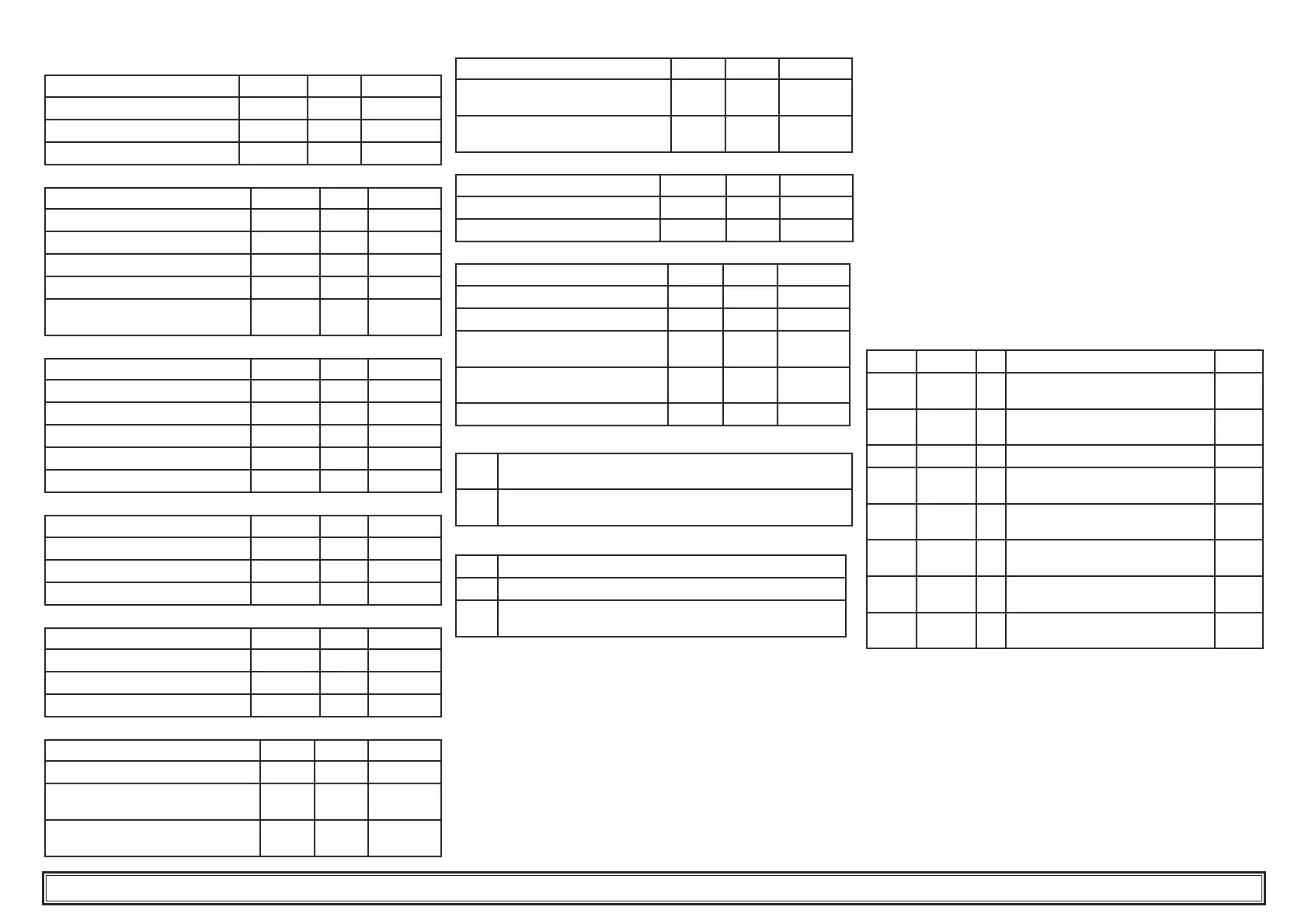
4.4.2 Temperature control
PARAMETER CODE TYPE DEFAULT
Temperature control set point
SEt
D
--
Temperature control differential
dIF
D
4.0
Set point lower limit
LI5
U
5.0
4.4.3 B1 sensor parameters
PARAMETER CODE TYPE DEFAULT
High temperature con guration
cHAI
U
0
High temperature alarm
HAI
D
60.0
Low temperature alarm
LAI
D
-20.0
Sensor calibration
CAI
U
0.0
Low temperature alarm reset
differential
dbI
U
1.0
4.4.4 B2 sensor parameters
PARAMETER CODE TYPE DEFAULT
High temperature con guration
cHA2
U
0
High temperature alarm
HA2
U
60.0
Low temperature alarm
LA2
U
3.0
Sensor calibration
CA2
U
0.0
B2 sensor presence
Ab2
U
1.0
4.4.5 B3 sensors parameters
PARAMETER CODE TYPE DEFAULT
High temperature alarm
HA3
U
60.0
Low temperature alarm
LA3
U
-20.0
Sensor calibration
CA3
U
0.0
4.4.6 B5 sensors parameters
PARAMETER CODE TYPE DEFAULT
High temperature alarm
HA5
U
60.0
Low temperature alarm
LA5
U
-20.0
Sensor calibration
CA5
U
0.0
4.4.7 Compressor parameters
PARAMETER CODE TYPE DEFAULT
Compressor rotation
rot
D
1
Compressor 1 operation hour
counter
HI
D
-
Compressor 2 operation hour
counter
H2
D
-
PARAMETER CODE TYPE DEFAULT
Compressor 1 hour counter
threshold
tHI
U
0
Compressor 2 hour counter
threshold
tH2
U
0
4.4.8 Pump parameters
PARAMETER CODE TYPE DEFAULT
Pump stop delay
dP5
U
5
Pump start delay
dPA
U
5
4.4.9 Antifreeze heater parameters
PARAMETER CODE TYPE DEFAULT
Set point adjustment (B1)
SEA
U
7.0
Temperature control differential (B1)
dIA
U
1.0
Antifreeze heater operating mode
(see para. 4.4.8.1)
FUA
U
0
Antifreeze heater activation mode
(see para. 4.4.8.2)
AbrA
U
2
Activation set point (B3)
ArA
U
5.0
4.4.9.1 FUA antifreeze heater operating mode
0
Temperature control by B1, activation by B3 (ambient
temperature sensor)
1
Temperature control by B3 (ambient temp. sensor) with
ARA set point.
4.4.9.2 AbrA antifreeze heater activation mode
0
Activation only when controller is ‘On’
1
Activation also when controller is ‘Off’
2
Activation also when controller is ‘Off’. During heater opera-
tion the pump is activated.
4.5 Parameter management
4.5.1 Temperature setting (see fi g.1)
1. 1. Turn the main swicth (QS) to “ON” and wait for the temperature
visualization.
2. Press buttons “P3” and “P5” together, to enter into “dIrE” (D)
parameters.
3. Press button “P4” to select “SEt” parameter, press the button
“P5” to con rm.
4. Change the value, using the up and down arrow buttons “P3” and
“P4”, then press button “P5” to con rm.
6. Press the button “P3” to return on “dIrE” parameter.
7. Press the button “P5” to exit.
4.5.2 Differential setting (see fi g.1)
1. Turn the main swicth (QS) to “ON” and wait for the temperature
visualization.
2. Press buttons “P3” e “P5” together, to enter into “dIrE” (D)
parameters.
3. Press button two times “P4” to select “diF” parameter, press the
button “P5” to con rm.
4. Change the value, using the up and down arrow buttons “P3” and
“P4”, then press button “P5” to con rm.
6. Press the button two times “P3” to return on “dIrE” parameter.
7. Press the button “P5” to exit.
4.5.3 Visualization sensors B1,B2...
“B1” is the “set” sensor of the macchine.
1. Start the chiller.
2. Press the button “P4” to visualize the temperature of the next sen-
sor.
3. Press the button “P5” to visualize the sensors “b01” ..“b02”....
It is recommended to leave on the display the B1 “set” sensor.
4.6 Alarms management
4.6.1 Digital input alarms
ID CODE LED DESCRIPTION RESET
ID1
HPI
L5
High pressure alarm 1 from pres-
sure switch
M
ID2
LPI
L6
Low pressure alarm 1 from pres-
sure switch
M
ID3
tP
L7 Pump thermal cutout alarm M
ID4
LL
L8
Water tank low water level alarm /
No water ow
A
ID6
HP2
L5
High pressure alarm 2 from pres-
sure switch
M
ID7
LP2
L6
Low pressure alarm 2 from pres-
sure switch
M
ID1+
ID2
PII
L9
Protection alarm compressor 1
/ Phases monitor
M
ID6+
ID7
PI2
L9
Protection alarm compressor 2
/ Phases monitor
M