English
4/8
ICE076-116
4 Control
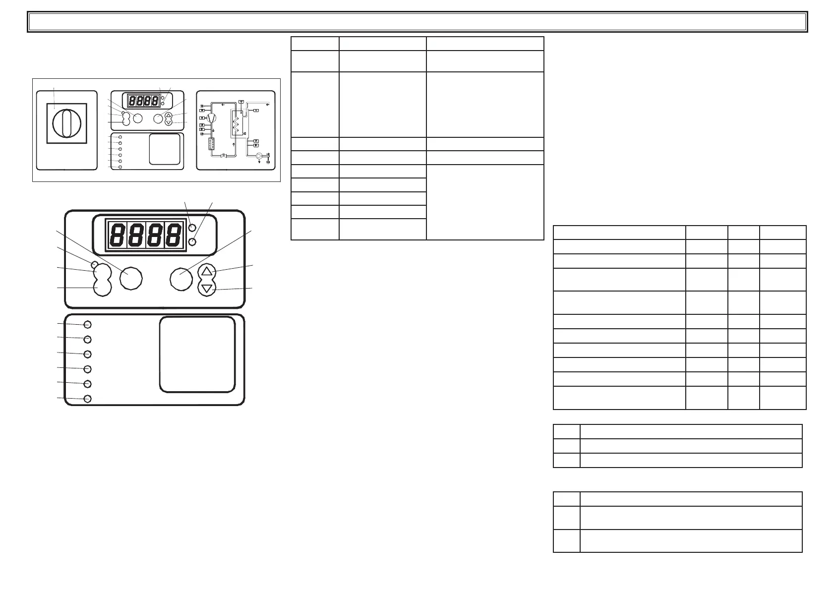
4.1 Control panel
Fig.1
LIV Low water level
PI
enter
Low pressur e
Pump al arm
High pressure
on
HP
TP
LP
off
C
F
I
O
Power supply
PS
4L3L0P
L5
L6
L7
L8
L9
L1
P6
P1
P2
P5
P3
P4
L2
Compr essor alarm
alarms
WATER
OUT
WATER
IN
LIV Low wat er level
PI
enter
Low pressure
Pump alarm
High pressure
on
HP
TP
LP
off
C
F
Power supply
PS
4L3L
L5
L6
L7
L8
L9
L1
P6
P1
P2
P5
P3
P4
L2
Compressor alarm
alarms
P0 Isolator switch.
P1 On key: activates the controller.
P2 Off key: deactivates the controller.
P3 UP key: used to increase the value of a modi able parameter.
P4 DOWN key: used to decrease the value of a modi able parameter
P5 Enter key: used to con rm modi cations to parameters.
P6 Alarms key: used to reset all manual reset alarms.
LED ON FLASHING
L1: yellow
Controller is receiving
power
L2: green
Controller is On With the controller receiving power
and ‘Off’: an antifreeze heater is
on.
With the controller receiving power
and ‘On’: compressor called for,
but wating for a delay time to
elapse.
L3: red
°C unit of measurement
L4: red
°F unit of measurement
L5: red
High pressure alarm
USER Loop or FACTORY program-
ming mode
L6: red
Low pressure alarm
L7: red
Pump temperature alarm
L8: red
Low water level alarm
L9: red
Compressor protection
alarm
4.2 Starting the chiller
• Connect the power supply to the machine by turning the main
isolator switch QS [P0] to ON.
• Turn the chiller ‘ON’ by pressing the key [P1].
• Set the desired temperature on the controller.
Phases Monitor
If appears on display the alarm “PI1/PI2 “, during the start up, the
user must verify the wiring of the input terminals of the disconnecting
switch.
4.2.1 Adjustments at commissioning
a) Temperature setting. To adopt a new setting, see heading 4.5.
b) Verify correct operation of the pump, using the pressure gauge (read
P1 and P0) and checking the pressure limit values (Pmax and Pmin)
indicated on the pump data plate.
P1 = pressure with pump ON
P0 = pressure with pump OFF
Pmin < (P1-P0) < Pmax
- Example n°1.
Conditions:
closed circuit, pressure P0 = 2 bar
pump data plate values: Pmin 1 bar/ Pmax 3 bar
adjust the valve outlet to give a pressure of 3 bar < P1< 5 bar
- Example n°2.
Conditions:
open circuit, pressure P0 = 0 bar
pump data plate values: Pmin 1 bar/ Pmax 3 bar
adjust the valve outlet to give a pressure of 1 bar < P1 < 3 bar
c) Verify correct operation of the pump similarly under normal running
conditions.
Check also that the amperage of the pump is within the limits indi-
cated on the data plate.
d) Switch off the chiller and proceed to top up the hydraulic circuit at
the “SET” temperature.
e) Check that the temperature of the “treated” water does not fall
below 5 °C and that the ambient temperature in which the hydraulic
circuit operates does not fall below 5 °C. If the temperature is too
low, add the appropriate quantity of glycol, as explained under head-
ing 3.3.2
4.3 Stopping the chiller
When chiller operation is no longer required, turn the chiller off as fol-
lows: press key [P2] to switch the controller ‘Off’.
Do not turn off the main switch QS [P0] to ensure that any antifreeze
protection devices will still receive electrical power.
4.4 Parameter settings
General
There are two levels of protection for parameters:
a) Direct (D): with immediate access, User-changeable;
b) Password protected (U): password required for access; Factory-set
parameters.
4.4.1 Chiller parameters
PARAMETER CODE TYPE DEFAULT
Unit of measurement
C-F
U
0
Unit address
Adr
U
1
Remote on / off enabling
(see para. 4.4.1.1).
rE
U
0
Alarm relay management (see
para. 4.4.1.2)
rAL
U
0
Digital output 3 con guration
Ud3
U
0
Digital output 6 con guration
Ud6
U
0
Pump thermal alarm management
AtP
U
1
Chiller hour counter
HUL
U
-
Chiller hour counter
HUH
U
-
Chiller hour counter alarm
threshold
tHU
U
0
4.4.1.1 Remote On / Off mode
0
Remote On/Off disabled
1
Remote On/Off enabled together with local On/Off
2
Remote On/Off only, local On/Off disabled
4.4.1.2 Alarm relay management
0
Relay normally deactivated, excited by an alarm.
1
Relay normally excited (also with control OFF), deactivated
by an alarm.
2
Relay normally excited (only with control ON), deactivated
by an alarm or with control OFF.
 Loading...