2
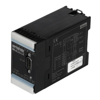
Digital Pump Control Module
Series PQDXXA-Z10
Installation and Setup Manual
Bulletin HY30-3255-INST/UK
Parker Hannifin Manufacturing Germany GmbH & Co. KG
Pump & Motor Division Europe
Chemnitz, Germany
Setup Manual for digital pump control module PQDXXA-Z10 to operate electro hydraulic
proportional controls for PVplus.
Contents Page
1. Introduction ............................................................................................................................... 3
Dimensions ..............................................................................................................................3
Ordering Codes ........................................................................................................................ 3
Name plates .............................................................................................................................4
Block diagram...........................................................................................................................5
Features: ..................................................................................................................................5
Technical Data ..........................................................................................................................6
Signal flow chart .......................................................................................................................7
Control loop quality ..................................................................................................................7
2. Security advice .........................................................................................................................8
Symbols ...................................................................................................................................8
Name plates, markings ............................................................................................................8
Work with electronics ...............................................................................................................8
3. Important notes ........................................................................................................................8
Intended usage ........................................................................................................................8
General instructions .................................................................................................................8
Liability .....................................................................................................................................8
Storage .....................................................................................................................................8
4. Mounting / Installation..............................................................................................................8
Scope of Supply .......................................................................................................................8
Mounting ..................................................................................................................................8
Installation and removal of module from the rail .......................................................................9
Operating limits ........................................................................................................................9
Electrical Connection ...............................................................................................................9
Electrical Interfacing .................................................................................................................9
Wiring diagram .......................................................................................................................10
Digital Inputs ..........................................................................................................................11
Enable p/Q-control .................................................................................................................11
Enable ramp ...........................................................................................................................11
Analog Inputs .........................................................................................................................11
Displacement command signal input .....................................................................................11
Pressure command signal input ............................................................................................. 12
Horse power command signal input .......................................................................................12
Sensor signals ........................................................................................................................13
Analog Outputs ......................................................................................................................16
Digital outputs ........................................................................................................................16
5. Programming ..........................................................................................................................18
6. Operating Parameters ............................................................................................................20
6.1 MODE – Standard (STD) .................................................................................................20
6.2 MODE – EXPERT (EXP)..................................................................................................21
6.3 MODE – Offline (PARKER EXP) ......................................................................................32
6.4 PID Parameter Setting .....................................................................................................35
6.5. Important settings and diagnosis values .........................................................................37
7. Connectind diagram for proportional displacement control; code ...FPV. ........................38
8. Connecting diagram for p/Q-control; (all versions) ............................................................ 39
9. Trouble shooting guide ..........................................................................................................40

 Loading...


