EasyManua.ls Logo

ParTech ASLD2200 - Electrical Connections

Default Icon
30 pages
Print Icon
To Next Page IconTo Next Page
To Previous Page IconTo Previous Page
Loading...
ASLD2200 - Instruction Manual
5.2 Electrical Connections
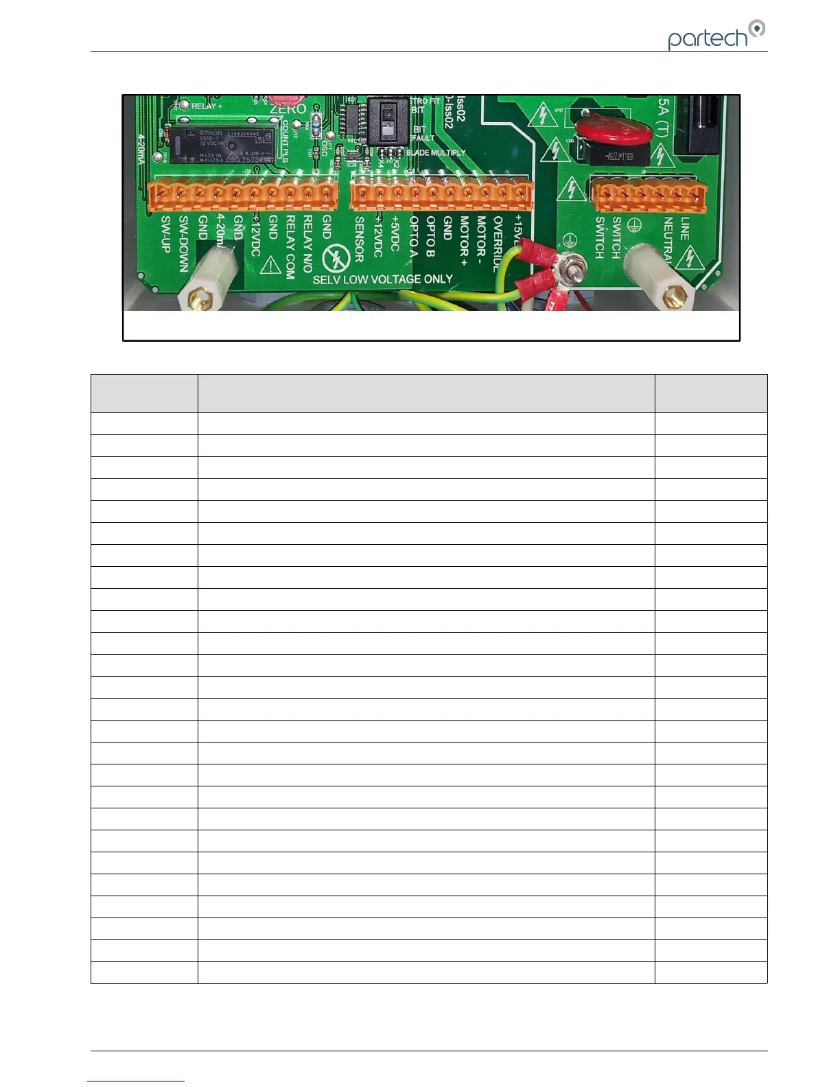
Number Function Colour of
Internal Wiring
Remote Up Switch
White/Black
Remote Down Switch
Orange/Black
Remote Switch Common
Yellow/Black
4-20 mA Hi (+)
4-20 mA Lo (-)
Regulated 12v DC Output
0v DC
Limit Relay, 0% and/or 100%
0v DC
Sensor Lo
Blue
Sensor 12v
Brown
5v DC to Encoder
Red
Input 1 from Encoder
Blue
Input 2 from Encoder
Yellow
0v DC to Encoder
Black
Nominal 18v DC to Motor (+ve)
Green
Nominal 18v DC to Motor (-ve)
Red/Brown
Not Used
Not Used
To mains isolator
Red/Brown
To mains isolator
Red/Brown
Earth
No connection
Neutral
Live
The ASLD2200 requires a mains power supply to operate this can be either 115 or 230v AC.
Unless specifically advised to do so, do not make changes to the internal wiring.
103370IM Issue 10 Date 19/03/2018 Page 13 of 30
PCBA SHOWING TERMINATION DETAILS