ASLD2200 - Instruction Manual
6.3 Links
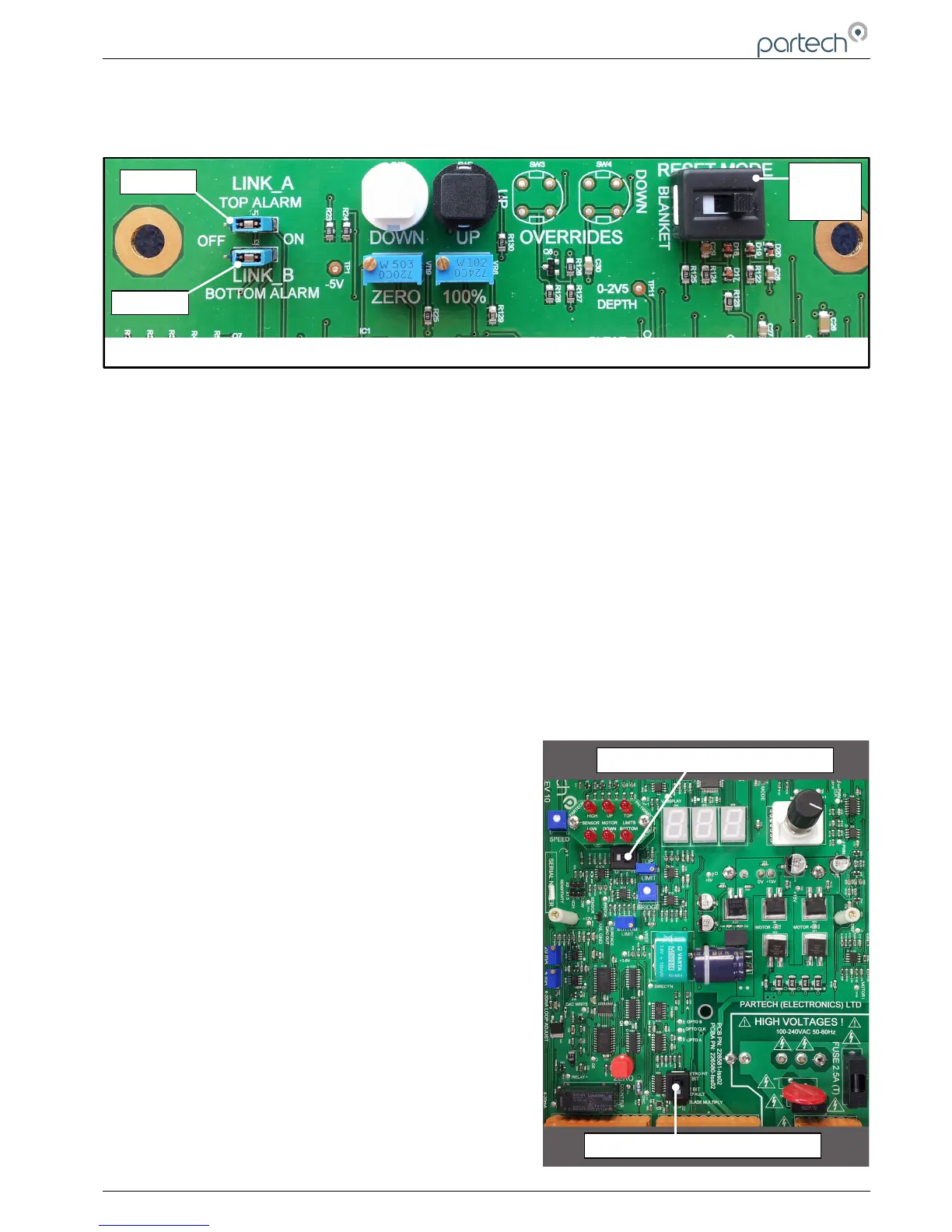
The circuit board has two sets of links (LINK_A & LINK_B), and a ‘Reset Mode’ switch that need to be set in the
correct position for the application.
Link A
When a jumper is placed the ‘ON’ position the limit relay will activate when the top limit LED is on – display is reading
100%. The factory default is for this jumper to be in the ‘ON’ position.
Link B
When a jumper is placed the ‘ON’ position the limit relay will activate when the bottom limit LED is on – display is
reading 0%. The factory default is for this jumper to be in the ‘ON’ position.
RESET MODE SWITCH
Switch to ‘RIGHT’ with white ident towards ‘BLANKET’ label
On power up, either during commissioning or after a power failure the sensor will immediately start to search for the
sludge blanket.
Switch to ‘LEFT’ with white ident towards ‘TOP’ Label
On power up, either during commissioning or after a power failure the sensor will lift to the top limit. It will then wait for
the down button to be pressed.
This switch setting will only effect operation with the rotary switch on ‘automatic’. Other settings of the rotary switch will
override this feature.
The factory setting for this switch is to the right (with white ident
showing towards ‘BLANKET’)
Switches SW7 & SW9 (as illustrated in the diagram on the right) are
set in the position shown. Do not move these switches. They are
intended for future enhancements of ASLD operation.
103370IM Issue 10 Date 19/03/2018 Page 15 of 30