Configuring LASAIR II CommunicationsConfiguring LASAIR II Communications
LASAIR II Operator’s ManualLASAIR II Operator’s Manual
PagePage
7-37-3
Ethernet Communications Setup ScreenEthernet Communications Setup Screen
Figure 7-2 is the Ethernet communications setup screen where all networkFigure 7-2 is the Ethernet communications setup screen where all network
addressing parameters are set, and various network communication protocolsaddressing parameters are set, and various network communication protocols
are enabled or disabled. When a network address is changed, the LASAIR IIare enabled or disabled. When a network address is changed, the LASAIR II
must be rebooted. A pop-up message must be rebooted. A pop-up message informs you of this when you try to informs you of this when you try to exitexit
the screen. The various setup parameters are discussed below.the screen. The various setup parameters are discussed below.
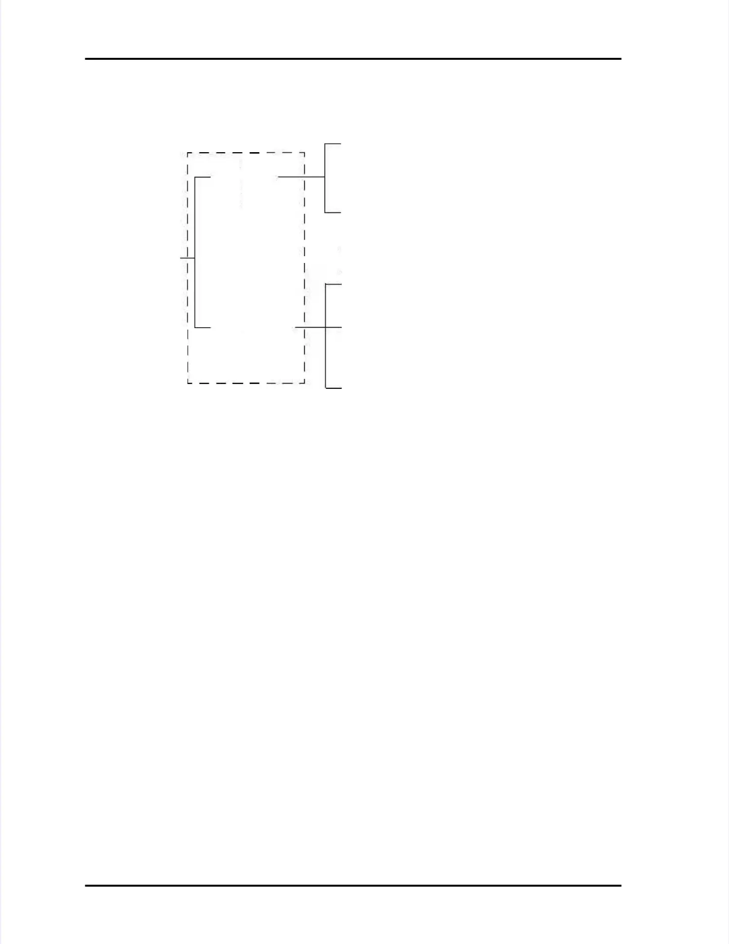
Figure 7-1: Setup paths for communications modesFigure 7-1: Setup paths for communications modes
Serial screenSerial screen
Network screenNetwork screen
(Ethernet)(Ethernet)
LASAIR IILASAIR II
communicationcommunication
modesmodes
❏❏
Enable Web ServerEnable Web Server
(Select for web browser interface)(Select for web browser interface)
❏❏Enable TCP/IP Remote ModeEnable TCP/IP Remote Mode
(Select when operating in the(Select when operating in the
Remote Mode)Remote Mode)
❏❏Enable TCP/IPEnable TCP/IP
(Select for PMS TCP/IP protocol(Select for PMS TCP/IP protocol
with Facility Net and Remote Mode)with Facility Net and Remote Mode)
❏❏PMS Multi-DropPMS Multi-Drop
(Select for MiniLaz emulation(Select for MiniLaz emulation
with Facility Net)with Facility Net)
❏❏
LASAIR IILASAIR II
(Select for normal RS-232(Select for normal RS-232
communications)communications)
COMM Setup ScreensCOMM Setup Screens
 Loading...