Whendesigningandinstallingductwork,considerthe following: CONFIGURING UNITS FOR DOWNFLOW (VERTICAL)
DISCHARGE
UNIT DAMAGE HAZARD
Failure to follow this caution may result in damage to unit
components.
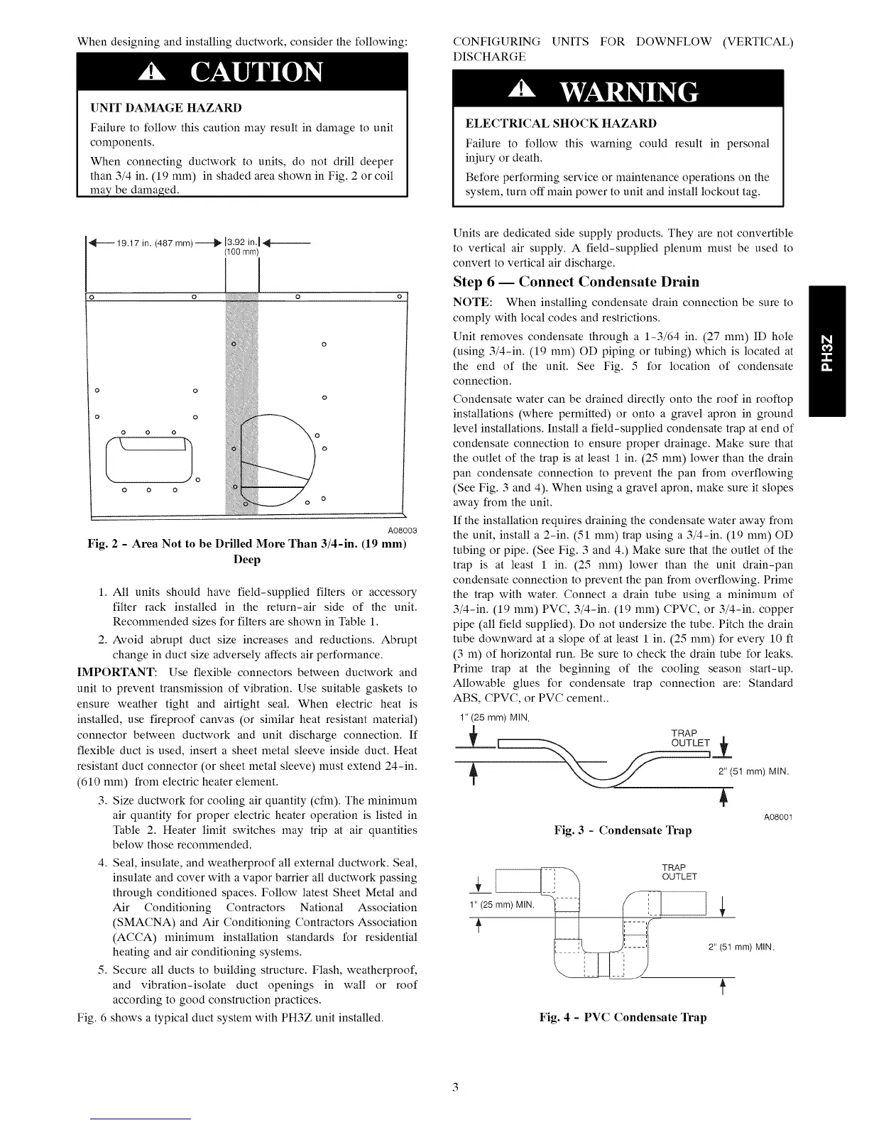
When connecting ductwork to units, do not drill deeper
than 3/4 in. (19 mm) in shaded area shown in Fig. 2 or coil
may be damaged.
ELECTRICALSHOCK HAZARD
Failure to follow this warning could result in personal
iniury or death.
Before performing service or maintenance operations on the
system, turn off main power to unit and install lockout tag.
o
19.17 in. (487 mm) .----.4_ 13.92 in.I _--
(100 ram)
o
o
o o
o o o
A08003
Fig. 2 - Area Not to be Drilled More Than 3/4-in. (19 mm)
Deep
1. All units should have field-supplied filters or accessory
filter rack installed in the return-air side of the unit.
Recommended sizes for filters are shown in Table 1.
2. Avoid abrupt duct size increases and reductions. Abrupt
change in duct size adversely affects air performance.
IMPORTANT: Use flexible connectors between ductwork and
unit to prevent transmission of vibration. Use suitable gaskets to
ensure weather tight and airtight seal. When electric heat is
installed, use fireproof canvas (or similar heat resistant material)
connector between ductwork and unit discharge connection. If
flexible duct is used, insert a sheet metal sleeve inside duct. Heat
resistant duct connector (or sheet metal sleeve) must extend 24-in.
(610 mm) from electric heater element.
3. Size ductwork for cooling air quantity (cfm). The minimum
air quantity for proper electric heater operation is listed in
Table 2. Heater limit switches may trip at air quantities
below those recommended.
4. Seal, insulate, and weatherproof all external ductwork. Seal,
insulate and cover with a vapor barrier all ductwork passing
through conditioned spaces. Follow latest Sheet Metal and
Air Conditioning Contractors National Association
(SMACNA) and Air Conditioning Contractors Association
(ACCA) minimum installation standards for residential
heating and air conditioning systems.
5. Secure all ducts to building structure. Flash, weatherproof,
and vibration-isolate duct openings in wall or roof
according to good construction practices.
Fig. 6 shows a typical duct system with PH3Z unit installed.
Units are dedicated side supply products. They are not convertible
to vertical air supply. A field-supplied plenum must be used to
convert to vertical air discharge.
Step 6 -- Connect Condensate Drain
NOTE: When installing condensate drain connection be sure to
comply with local codes and restrictions.
Unit removes condensate through a 1-3/64 in. (27 mm) ID hole
(using 3/4-in. (19 mm) OD piping or tubing) which is located at
the end of the unit. See Fig. 5 for location of condensate
connection.
Condensate water can be drained directly onto the roof in rooftop
installations (where permitted) or onto a gravel apron in ground
level installations. Install a field-supplied condensate trap at end of
condensate connection to ensure proper drainage. Make sure that
the outlet of the trap is at least 1 in. (25 mm) lower than the drain
pan condensate connection to prevent the pan from overflowing
(See Fig. 3 and 4). When using a gravel apron, make sure it slopes
away from the unit.
If the installation requires draining the condensate water away from
the unit, install a 2-in. (51 mm) trap using a 3/4-in. (19 mm) OD
tubing or pipe. (See Fig. 3 and 4.) Make sure that the outlet of the
trap is at least 1 in. (25 mm) lower than the unit drain-pan
condensate connection to prevent the pan from overflowing. Prime
the trap with water. Connect a drain tube using a minimum of
3/4-in. (19 mm) PVC, 3/4-in. (19 mm) CPVC, or 3/4-in. copper
pipe (all field supplied). Do not undersize the tube. Pitch the drain
tube downward at a slope of at least 1 in. (25 mm) for every 10 ft
(3 m) of horizontal run. Be sure to check the drain tube for leaks.
Prime trap at the beginning of the cooling season start-up.
Allowable glues for condensate trap connection are: Standard
ABS, CPVC, or PVC cement..
1"(25 mm) MIN.
._ TRAP
2" (51 mm) MIN.
A08001
Fig. 3 - Condensate Trap
1" (25 mm) MIN.
TRAP
"(51 ram)MIN.
Fig. 4 - PVC Condensate Trap