Model Size
048
049
060
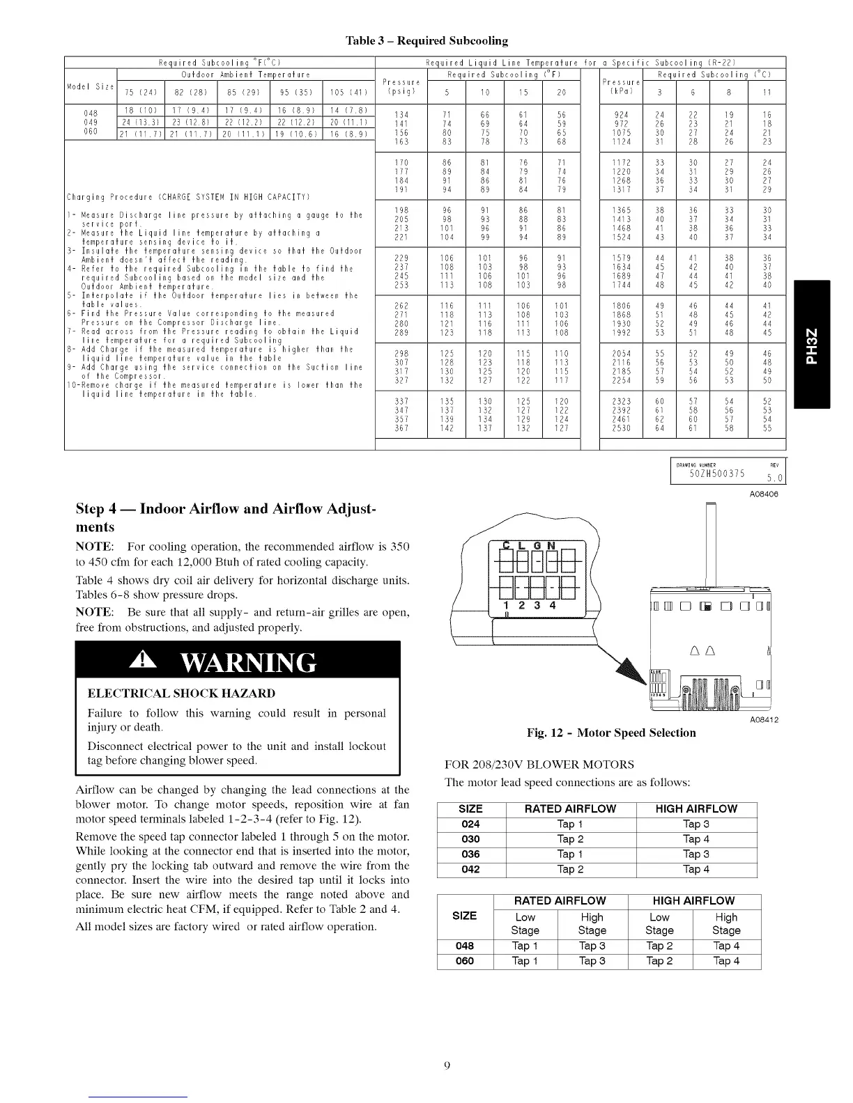
Required Subcooling °F(°C)
Outdoor Ambient Temperature
75 (24) 82 (28) 85 (29) 95 (35) 105 (41)
18 (10) 17 (9 4) 17 (9 4} 16 (8 9) 14 (7 8)
2a (133) 23 (128) 22 (12 2} 22 (12 2) 20 (11 1/
21 (11 7) 21 111 7) 20 (11 1) 19 (10 6) 16 (8 9)
Charging Procedure (CHARGE SYSTEM IN HIGH CAPACITY)
- Measure Discharge line pressure by attaching a gauge to the
service port
2- Measure the Liquid line temperature by attaching a
temperature sensing device fo it
3- Insulate the temperature sensing device so that the Outdoor
Ambient doesn't affect the reading
4- Refer to the required Subcooling in the table to find the
required Subcooling based on the model size and the
Outdoor Ambient temperature
5- Interpolate if tile Outdoor temperature lies in between the
fable values
6- Find the Pressure Value corresponding to the measured
Pressure on the Compressor Discharge line
7- Read across from the Pressure reading to obtain the Liquid
line temperature for a required Subcooling
8- Add Charge if the measured temperature is higher than the
liquid line temperature value in the table
9- Add Charge using the service connection on the Suction line
of the Compressor
O-Remove charge it the measured temperature is lower than the
liquid line temperature in the table
Table 3 - Required Subcooling
Required Liquid Line Temperature for a Specific Subcooling (R-22)
Required Subcoolin9 (°F) Required Subcooling (°C)
Pressure Pressure
(psig) 5 10 15 20 (kPa) 3 6 8 11
134 71 66 61 56 924 24 22 19 16
141 74 69 64 59 972 26 23 21 18
156 80 75 70 65 1075 30 21 24 21
163 83 78 73 68 1124 31 28 26 23
170 86 81 76 71 1172 33 30 27 24
171 89 84 79 14 1220 34 31 29 26
184 91 86 81 76 1268 36 33 30 27
19! 94 89 84 79 1317 37 34 31 29
198 96 91 86 81 1365 38 36 33 30
205 98 93 88 83 1413 40 37 34 31
213 101 96 91 86 1468 4! 38 36 33
221 104 99 94 89 1524 43 40 37 34
229 106 101 96 91 1579 44 4! 38 36
237 108 103 98 93 1634 45 42 40 37
245 111 106 101 96 1689 47 44 41 38
253 113 108 103 98 1744 48 45 42 40
262 116 111 106 101 1806 49 46 44 41
271 118 113 108 103 1868 51 48 45 42
280 121 116 111 I06 1930 52 49 46 44
289 123 118 113 108 1992 53 51 48 45
298 125 120 115 110 2054 55 52 49 46
307 128 123 118 I13 2116 56 53 50 48
317 130 125 120 115 2185 57 54 52 49
327 132 127 122 117 2254 59 56 53 50
337 135 130 125 I20 2323 60 57 54 52
347 137 132 127 122 2392 6! 58 56 53
357 139 134 129 12A 2461 62 60 57 54
367 142 137 132 127 2530 64 61 58 55
Step 4 -- Indoor Airflow and Airflow Adjust-
ments
NOTE: For cooling operation, the recommended airflow is 350
to 450 cfm for each 12,000 Btuh of rated cooling c@acity.
Table 4 shows dry coil air delivery for horizontal discharge units.
Tables 6-8 show pressure drops.
NOTE: Be sure that all supply- and return-air grilles are open,
free from obstructions, and adjusted properly.
ELECTRICAL SHOCK HAZARD
Failure to follow this warning could result in personal
injury or death.
Disconnect electrical power to the unit and install lockout
tag before changing blower speed.
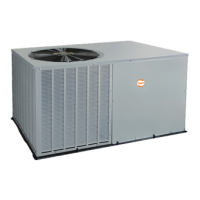
Airflow can be changed by changing the lead connections at the
blower motor. To change motor speeds, reposition wire at fan
motor speed terminals labeled 1-2-3-4 (refer to Fig. 12).
Remove the speed tap connector labeled 1 through 5 on the motor.
While looking at the connector end that is inserted into the motor,
gently pry the locking tab outward and remove the wire from the
connector. Insert the wire into the desired tap until it locks into
place. Be sure new airflow meets the range noted above and
minimum electric heat CFM, if equipped. Refer to Table 2 and 4.
All model sizes are factory wired or rated airflow operation.
DRAWING _UMBER REV !
50ZH500375 5.0
AO8406
1234
I
Fig. 12 - Motor Speed Selection
AO8412
FOR 208/230V BLOWER MOTORS
The motor lead speed connections are as follows:
SIZE RATED AIRFLOW HIGH AIRFLOW
024 Tap 1 Tap 3
030 Tap 2 Tap 4
036 Tap 1 Tap 3
042 Tap 2 Tap 4
RATED AIRFLOW HIGH AIRFLOW
SIZE Low High Low High
Stage Stage Stage Stage
048 Tap 1 Tap 3 Tap 2 Tap 4
060 Tap 1 Tap 3 Tap 2 Tap 4