AAM
™
1662 User Manual
Page 14 http://aa.peavey.com copyright 2001 All Rights Reserved
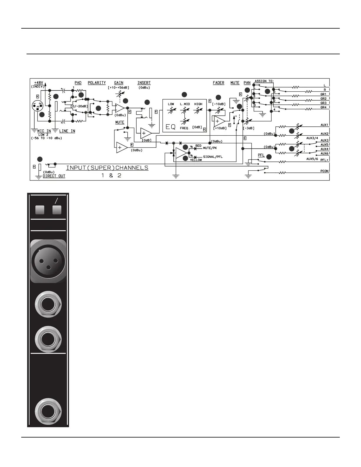
Input Channels 1 & 2 Rear Panel Features
Input channels 1 & 2, also called “Super Channels”, feature additional rear panel buttons for polarity and pad. In addition, the
mid frequency has a wider range of adjustment, and they include their own switchable phantom power supply.
1.
2.
3.
4.
5.
6.
PAD SWITCH Two position push switch toggles a 20 dB resistive pad circuit before the first gain
stage. The pad is active when the switch is in the DOWN position.
POLARITY SWITCH (PHASE) Two position switch toggles the polarity of balanced input sig-
nals 180 degrees. The phase is reversed when the switch is in the DOWN position.
BALANCED MICROPHONE INPUT Female XLR connector for terminating balanced, low
impedance microphone circuits. Pin 2 is positive and +48 V DC is applied to pins 2 and 3 via a
resistive network when the front panel Phantom Power switch is ON. (See page 28.)
BALANCED LINE INPUT Female 1/4” TRS connector for terminating balanced low or high
impedance line level circuits. Tip is positive, ring is negative. This circuit is wired in parallel with
the female XLR connector. Connecting to this input will not disable the XLR input connector, so
both inputs should NOT be used simultaneously.
INSERT JACK Female 1/4” TRS connector for terminating two, single-ended (unbalanced) line
level circuits. The tip is a line output and carries the signal after the first gain stage (post gain).
The ring is a line input and feeds the secondary gain circuit just before the equalization stage.
Inserting a TRS male connector into this jack will break the circuit of the input channel. A com-
plete loop must be made to pass audio through the jack. Inserting a plug so that only the tip makes
connection will provide a line output only, but will break the connection. If a complete connection
is required when using this jack as a line output, it must be made by completing the loop at the
plug.
DIRECT OUT Female 1/4” TS connector for terminating a single unbalanced line level audio out-
put. The signal present at this connector is after the fader and channel mute (post fader and post
mute).
1
2
3
4
5
6
14
13
15
7
8
9
10
11
12
16
17
 Loading...