AAM
™
1662 User Manual
Page 24 http://aa.peavey.com copyright 2001 All Rights Reserved
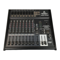
Group 5/6 Outputs Rear Panel Features
The Group 5/6 feature provides two additional buses that can be assigned to the L/R, Group 1/2, Group 3/4, Aux 1 or Aux 2
buses. These groups also include their own output. Only input channels 9-16 can be assigned to these groups.
UNBALANCED OUTPUT (Typ of all Group outputs) Female 1/4” TS
connector for terminating a single unbalanced line level audio out-
put. The signal present at this connector is after the final gain stage
and the main output Fader.
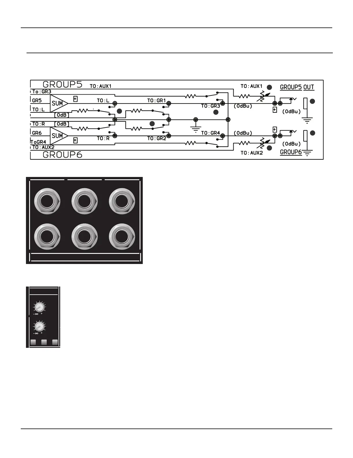
AUX 1 LEVEL This rotary control sends the Group 5 audio output
to the Aux 1 bus. The control sends the audio after the final gain.
Unity gain is represented by the 0 dB mark. (There is a detent to
indicate 0 dB.) The range of the control is infinity (OFF) to +10 dB.
AUX 2 LEVEL This rotary control sends the Group 6 audio output
to the Aux 2 bus. The control sends the audio after the final gain.
Unity gain is represented by the 0 dB mark. (There is a detent to
indicate 0 dB.) The range of the control is infinity (OFF) to +10 dB.
L/R SWITCH This push button switch assigns both audio signals
(Group 5 & 6) to the main Left/Right output buses. When the
switch is in the DOWN position, the audio from Group 5 is assigned
to the Left bus, and the audio from Group 6 is assigned to the Right
bus.
1/2 SWITCH This push button switch assigns both audio signals
(Group 5 & 6) to the Group 1/2 output buses. When the switch is in
the DOWN position, the audio from Group 5 is assigned to the
Group 1 bus, and the audio from Group 6 is assigned to the Group 2
bus.
3/4 SWITCH This push button switch assigns both audio signals
(Group 5 & 6) to the Group 3/4 output buses. When the switch is
in the DOWN position, the audio from Group 5 is assigned to the
Group 3 bus, and the audio from Group 6 is assigned to the Group 4
bus.
1.
2.
3.
4.
5.
6.
 Loading...