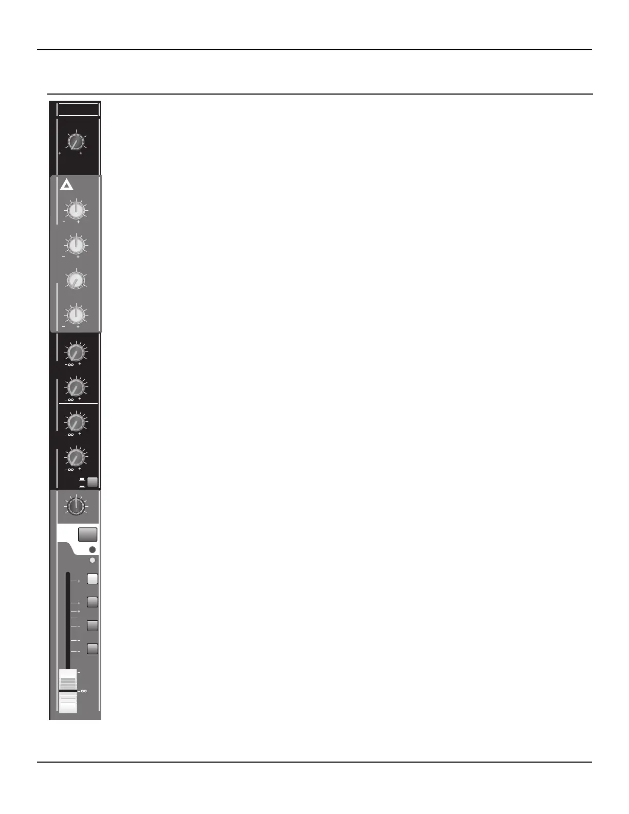
MIC/LINE GAIN CONTROL Rotary control adjusts the first gain stage of the input channel. The range
is +10 to +56 dB for microphone level inputs and -10 to +36 dB for line level inputs. The output of this gain
stage also drives the SIG/PFL LED.
EQUALIZATION Three-band equalizer. The high frequency shelving EQ is fixed at 12.5 kHz, the low
frequency at 80 Hz and the mid band filter is adjustable from 40 Hz to 1.2 kHz. All sections are adjustable
from -15 to +15 dB. The center position for each control is detented, and removes the filter from the signal
path.
AUX (PRE) SEND CONTROLS Aux 1 and Aux 2 are pre-fader foldbacks. Each control drives the corre-
sponding Aux bus, after the Aux 1/2 gain stage, and has a range of infinity (OFF) to +10 dB. A center
detent is provided at 0 dB and represents unity gain at the Aux 1/2 amplifier stage.
AUX (POST) SEND CONTROLS Aux 3, 4, 5 & 6 are post-fader foldbacks. The two controls drive
either the Aux 3/4 bus, or the Aux 5/6 bus, depending on the position of the AUX 3/4, AUX 5/6 push
switch. The default mode of AUX 3/4 is active when the switch is in the UP position. These post fader
sends are driven from the main channel, post fader gain stage, just before the channel assignment stage.
Each control has a range of infinity (OFF) to +10 dB. A center detent is provided at 0 dB and represents
unity gain at the post fader stage.
PAN CONTROL A single rotary control assigns the post fader audio, after the final channel gain stage to
any combination of the Odd (Left, Group 1, Group 3) or Even (Right, Group 2, Group 4) side of the main
output buses. Which buses are driven is determined by the position of the L/R, 1/2 and 3/4 Bus Assign
switches.
MUTE SWITCH This push button switch toggles the channel audio mute status. When the switch is in
the DOWN position all audio is muted, including the L/R, Group 1-4 and Aux 1-6 bus sends. The
MUTE/PK LED will illuminate RED when the channel is muted.
MUTE/PK LED This dual-function LED will illuminate solid RED when the channel is muted. When the
channel is not muted, this LED will flash to indicate audio clipping. Clipping indication is provided after
the first gain stage and after the EQ (pre-fader). The LED becomes active at 2 dB below the clipping point
at the output bus.
SIG/PFL SWITCH This push button switch toggles the channel audio onto and off of the PFL head-
phone bus. When the switch is in the DOWN position, the audio is included in the PFL mix and the PFL
(right master) meter (see page 28). The corresponding SIG/PFL LED will illuminate yellow when active.
SIG/PFL LED This dual-function LED indicates the status of the PFL assign and the audio signal level.
When the LED is illuminated with solid yellow, the channel is assigned to the PFL bus, as determined by
the SIG/PFL switch. When the channel is not assigned to the PFL bus, this LED will constantly indicate
the audio signal presence level (-15 dBu) after the EQ, and just before the fader.
BUS ASSIGN SWITCHES (L/R, 1/2, 3/4) Three switches for assigning the post fader audio to any com-
bination of the Left/Right, Group 1/2 or Group 3/4 output buses. The assignments are made in pairs when
the switch is in the DOWN position. To make an assignment to a single bus, the pan control is required.
When none of the assign switches are in the DOWN position, the channel audio signal will not appear at
the main output buses.
FADER 60 mm precision fader controls the channel’s main audio after the final gain stage and before the
channel assign switches. Unity gain is represented by the 0 dB mark. (There is no detent.) The range of
the fader is infinity (OFF) to +10 dB.
 Loading...