AAM
™
1662 User Manual
Page 20 http://aa.peavey.com copyright 2001 All Rights Reserved
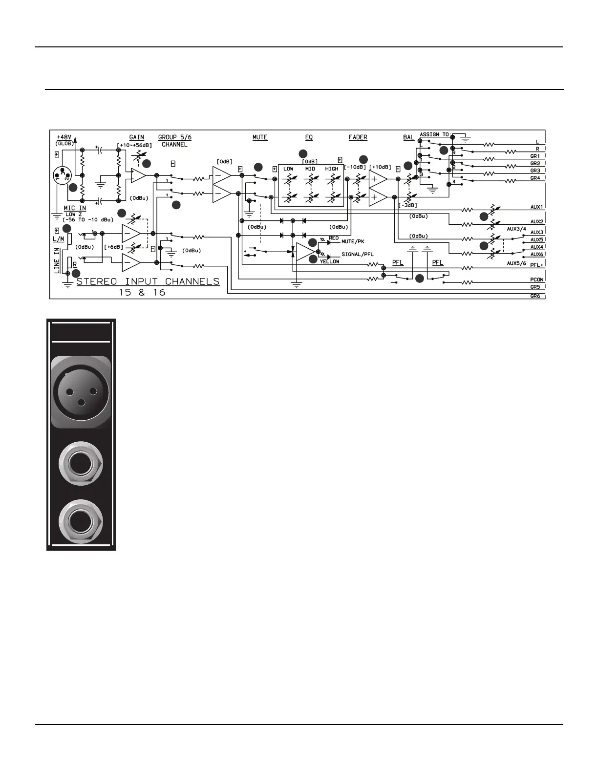
Input Channels 15 & 16 Rear Panel Features
In addition to the microphone input, channels 15 & 16 are full-featured stereo inputs. These channels feature dual gain stages
and EQ throughout the circuit. The stereo inputs are assignable to the Group 5/6 or L/R buses via a front panel select switch.
1.
2.
3.
BALANCED MICROPHONE INPUT Female XLR connector for terminating balanced, low
impedance microphone circuits. Pin 2 is positive and +48 V DC is applied to pins 2 and 3 via a
resistive network when the front panel Phantom Power switch is ON. (See page 28.)
LEFT/MONO Female 1/4” TS connector for terminating unbalanced low or high impedance line
level circuits. When both LEFT and RIGHT connectors are terminated, the signal from the LEFT
connector feeds the Left Main Channel and the Group 5 output bus. When this connector is used
alone, without the RIGHT connector, it will distribute the signal to both the L/R Main Channel,
Group 5 and Group 6 bus. The distribution of this input to the Group 5/6 bus is dependent on the
position of the front panel GP 5/6 CH 9 switch.
RIGHT Female 1/4” TS connector for terminating unbalanced low or high impedance line level cir-
cuits. The signal terminated to this connector feeds the Right Main Channel and the Group 6 out-
put bus. The distribution of this input to the Group 6 bus is dependent on the position of the front
panel GP 5/6 CH 9 switch.
2
1
4
10
3
12
11
13
5
5
6
7
8
9
14
15
 Loading...