AAM
™
1662 User Manual
Page 30 http://aa.peavey.com copyright 2001 All Rights Reserved
Specifications
MECHANICAL
PERFORMANCE
Dimensions (H x W x D)
Weight
Mounting
Connections
13.98” x 19” x 8.094” (35.51 cm x 48.26 cm x 20.56 cm) rack mounted
20.3 lbs. (9.2 kg)
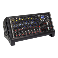
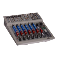
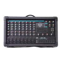
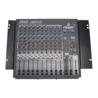
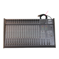
Eight EIA Space Rack Mount
Female XLR for microphone inputs, 1/4” TRS for line inputs, channel & L/R insert,
headphone output, 1/4” TS for stereo line inputs, direct outputs, L/R unbalanced out-
puts, control room I/O, Aux 1-6 outputs, Group outputs and tape inputs. Male XLR
for left, right, mono & Aux 1/2 outputs. Female RCA for L/R tape I/O.
Frequency Response:
Phase Response:
THD + Noise:
EIN:
Dynamic Range:
Common Mode Rejection Ratio:
Crosstalk:
Maximum Input Sensitivity
Settings:
Maximum Output Level:
Maximum Gain Range:
Input/Output Nominal
Level/Impedance:
Analog LED Metering:
+0 / -1 dB, 20 Hz ~ 20 kHz, referenced @ 1 kHz (maximum gain)
+/- 0.5 dB, 20 Hz ~ 20 kHz, referenced @ 1 kHz (minimum gain)
+/- 30 degrees 20 Hz ~ 20 kHz, referenced @ 1 kHz
0.005%, 22 kHz bandwidth measurement, +4 dBu signal with 20 dB headroom
-128 dBu (terminated at 150 Ohms)
100 dB, 22 kHz filter bandwidth measurement
70 dB typical at 1 kHz, maximum gain
-60 dB, 20 Hz ~ 20 kHz, measured between channels
-80 dBu (Gain & fader controls at maximum travel)
+26 dBu (balanced outputs)
+22 dBu (unbalanced outputs)
0 - 80 dB
Microphone inputs: +56 dBu / 2 k Ohms
Line level inputs: -0 dBu / 20 k Ohms
Balanced outputs: +4 dBu / 100 Ohms
Unbalanced outputs: 0 dBu / 10 Ohms
2x 12-segment LED ladder display meters for L/R & PFL buses
Top-most LED indicates level 2 dB below clipping
 Loading...