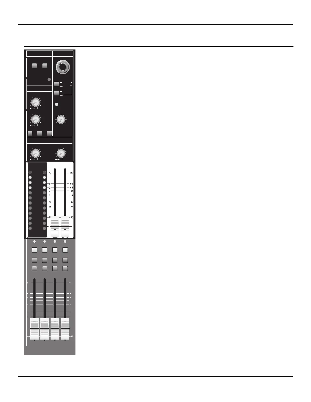
PHANTOM POWER SWITCHES Two push button switches 48 V DC phantom power ON or
OFF to channels 1 & 2 and/or channels 3-16. Phantom power must be ON when using condenser
microphones that require phantom power.
POWER LED This LED will illuminate green when mains power is supplied to the AAM 1662
via the rear panel power switch.
HEADPHONE JACK Female TRS connector supplies stereo audio to user-supplied headphones
after the front panel Headphone Level control. The audio level at this connector is suitable for
most stereo headphones (8-400 Ohms). The signals at this connector are dependent on the posi-
tion of the PFL and Headphone assign switches. When assigned to the Master L/R output buses,
the tip carries the Left signal and the ring carries the Right signal. NOTE: When the PFL system
is active, as indicated by the front panel PFL LED, the audio at the Headphone jack is derived
from the master PFL bus. This assignment is before the HP/CR Level control.
AUX 1/2 - 2 TRK SWITCH Push button switch assigns either the Aux 1/2 buses or audio con-
nected to the rear panel 2-TRK input to the headphone jack. This switch is active only when the
L/R SWITCH is in the down position (see below). When active, Aux 1 is present at the tip of the
Headphone jack, while Aux 2 appears at the ring. Likewise, the 2-TRK inputs Left signal would
be present at the tip, and Right to the ring of the Headphone jack.
L/R SWITCH Push button switch determines which audio signal appears at the Headphone
jack. When the switch is in the UP position, the main L/R output buses are assigned to the
Headphone jack. When the switch is in the DOWN position, the audio at the Headphone jack is
dependent on the position of the AUX 1/2 - 2 TRK SWITCH (see above).
PFL ACTIVE LED This yellow LED will flash steadily when the PFL circuit is in use. NOTE:
When the PFL circuit is active, the signal from the PFL audio bus becomes priority at the HEAD-
PHONE and CONTROL ROOM outputs. The front panel Right master meter is also re-assigned
to the PFL bus when this LED is active.
HP/CR CONTROL Rotary control adjusts any audio input that may be present on the
Headphone input. The control is after the Headphone assignment switches and before the final
headphone drive amplifiers. NOTE: This control also adjusts, simultaneously, the audio level at
the rear panel Control Room Output connectors (see previous page).
METERS Two 12-segment LED ladder displays provide metering for the Left and Right output
buses. The meter displays audio levels after the main bus fader and before the output balancing
amplifier. Zero dB on this meter represents a nominal output level of +4 dBu at the L/R balanced
outputs, and 0 dBu at the unbalanced outputs. NOTE: When the PFL system is active, the Right
meter displays the level of the PFL audio bus. When PFL is active, the Left meter is null and does
not display any audio levels.
FADERS 60 mm precision faders control the bus’s main audio output after the final gain stage
and before the balancing amplifiers (Left, Right bus only). This fader is the last adjustable control
before the output connectors for each bus.
Refer to page 27 for circuit/signal flow references for this section.
 Loading...