AAM
™
1662 User Manual
Page 18 http://aa.peavey.com copyright 2001 All Rights Reserved
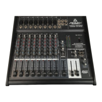
Input Channels 9 through 14 Rear Panel Features
Channels 9 through 14 feature a separate input that includes two line inputs that can be routed to separate output buses (Aux
5/6). These inputs can also be summed to the master channel circuit. A front panel level control is included for these inputs.
1.
2.
3.
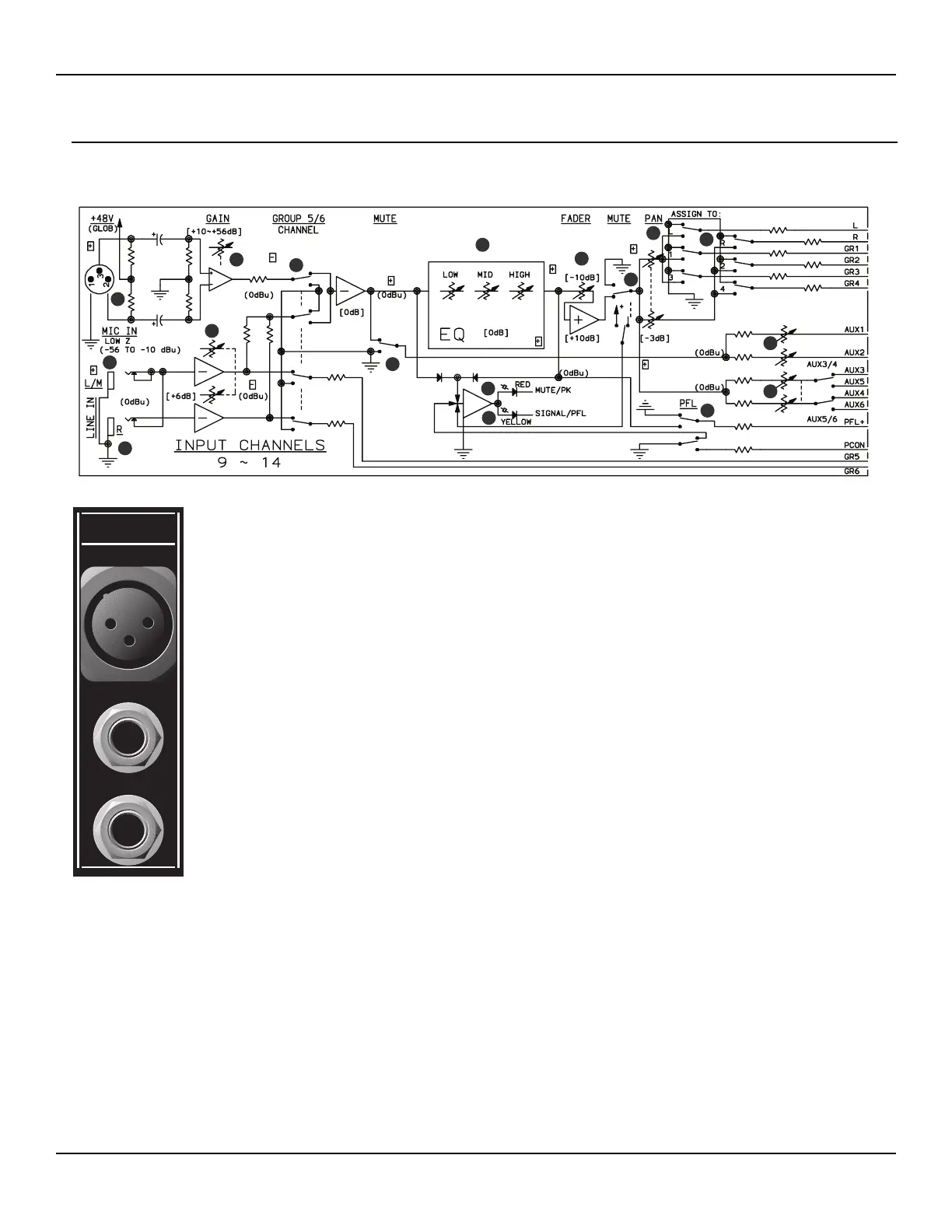
BALANCED MICROPHONE INPUT Female XLR connector for terminating balanced, low
impedance microphone circuits. Pin 2 is positive and +48 V DC is applied to pins 2 and 3 via a
resistive network when the front panel Phantom Power switch is ON. (See page 28.)
LEFT/MONO Female 1/4” TS connector for terminating unbalanced low or high impedance line
level circuits. When both Left and Right connectors are terminated, the signal from the Left con-
nector feeds the Main Channel and the Group 5 output bus. When this connector is used alone,
without the Right connector, it will distribute the signal to both the Main Channel, Group 5 and
Group 6 bus. The distribution of this input to the Group 5/6 bus is dependent on the position of
the front panel GP 5/6 CH 9 switch.
RIGHT Female 1/4” TS connector for terminating unbalanced low or high impedance line level cir-
cuits. The signal terminated to this connector feeds the Main Channel and the Group 6 output bus.
The distribution of this input to the Group 6 bus is dependent on the position of the front panel GP
5/6 CH 9 switch.
4
2
1
10
3
12
11
13
5
5
6
7
8
9
10
14
15
 Loading...