11 of 58
ISSUED: 10-30-09 SHEET #: 095-9297-7 07-11-11
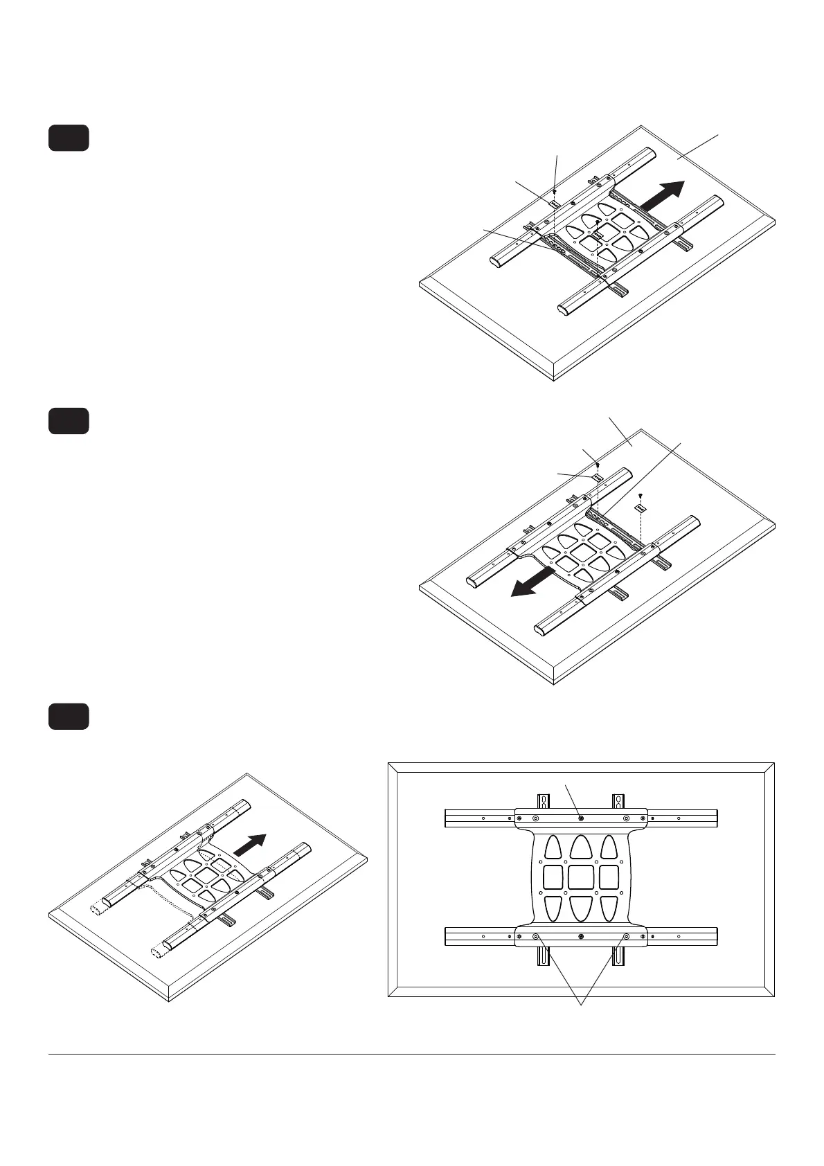
Slide universal adapter bracket to the opposite side
and align second display bracket with second set of
display mounting holes.
Hand thread screws through multi-washer, display
bracket, and spacer if used, into display as shown.
Tighten all screws.
3-3
SCREW
MULTI-WASHER
MULTI-
WASHER
DISPLAY
DISPLAY
BRACKET
VESA 200 x 200 or VESA 200 x 100 Mounting Pattern (Continued)
Align one display bracket with one set of display
mounting holes.
Begin with the shortest length screw, hand thread
screw through multi-washer and display brackets
into display as shown. Screw must make at least
three full turns into the mounting hole and fi t snug
into place. Do not over tighten. If screw cannot
make three full turns into the display, select a longer
length screw from the baffl ed fastener pack. Center
display brackets vertically and tighten screws.
NOTE: For displays with a bump-out or recessed
back, spacer may be used. Spacer goes between
display bracket and display.
3-2
SCREW
DISPLAY
DISPLAY
BRACKET
Center display brackets horizontally on back of display as shown in fi gure 3.3.
Tighten two 1/4-20 x 1.25" screws. Reinstall four 1/4-20 x .6" screws using 5mm allen wrench (I) into fi xed-stop
position 1 as shown in fi gure 3.4.
3-4
fi g. 3.4
1/4-20 x 1.25" SCREWS
FIXED STOP POSITION #1 WITH
1/4-20 x .6" SCREWS
fi g. 3.3