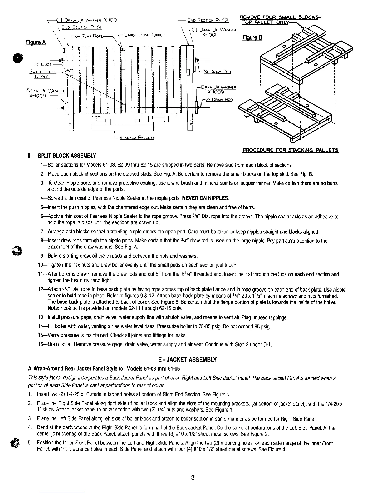
I:'ROC_"OUR lr FOR STACKING PALLtr'rq
II-- SPLITBLOCKASSEMBLY
1--Boiler sectionsfor Models61-08,62-09thru 62-15are shippedintwo parts.Removeskidfromeach blockof sections.
2--Place each blockof sectionsonthe stackedskids.See Fig.A. Becertainto removethesmallblocksonthetop skid.See Fig.B,
3--To clean nippleportsand removeprotectivecoating,usea wire brushandmineralspiritsor lacquerthinner.Makecertainthereare no burrs
aroundthe outsideedgeof the ports.
4--Spread a thincoatof PeerlessNippleSealerin the nippleports,NEVERON NIPPLES.
5--Insert the push nipples,withthe chamferededgeout. Makecertaintheyare cleanand freeofburrs.
6--Apply a thin coatof PeerlessNippleSealerto the ropegroove.Press5/8"Dia. ropeintothegroove.Thenipplesealeractsas an adhesiveto
holdthe ropein placeuntilthesecgonsare drawnup.
7--Arrange both blocksso that protrudingnippleentersthe open port.Caremustbetakento keepnipplesstraightand blocksaligned.
8--Insert drawrodsthroughthe nippleports.Makecertainthat the3/4"drawrod is usedonthe largenipple.Payparticularattentionto the
placementof the drawwashers.See Fig.A.
9--Before startingdraw,oil thethreadsand betweenthe nutsandwashers.
10--Tightenthe hexnutsanddraw boilerevenlyuntilthe smallpadsoneach sectionjust touch.
11--After boiler isdrawn,removethedraw rodsand cut 5" fromthe 6V4" threadedend.Inserttherod throughthe lugs oneachendsectionand
tightenthehex nutshandtight.
12--Attach3/8"Dia.ropeto basebackplateby layingropeacross topof backplateflange and in ropegrooveon eachendofbackplate.Usenipple
sealerto hold ropein place.Referto figures9 & 12.Attachbase backplate by meansof V4"-20x lr/2" machinescrewsandnutsfurnished.
Thebase backplateisattachedtobackof boiler.SeeFigure8.Becertainthatthe flangeportionofplate istowardsthe insideof the boiler.
Note: hook boltisprovidedonmodels62-11through62-15only.
13--Install pressuregage,drainvalve,water supplylinewith shutoffvalve,and meansto ventair.Plugunusedtappings.
14--Fill boilerwith water,ventingairas water levelrises.Pressurizeboilerto 75-85 psig.Do notexceed85 psig.
15--Verifypressureis maintained.Checkalljointsand fittingsfor leaks.
16--Drain boiler.Removepressuregage,drain valve,watersupplyand airvent.ContinuewithStep2 underD-1.
E - JACKET ASSEMBLY
A.Wrap-AroundRearJacketPanelStylefor Models61-03thru 61-06
Thisstylejacket designincorporatesa BackJacketPanelaspart of eachRightand Left SideJacketPanel.TheBack JacketPanelis formedwhena
portion of each SidePanelis bent atperforationsto rearof boile_:
I, Inserttwo (2) 1/4-20x 1"studs intapped holesat bottomof RightEndSection.SeeFigure t.
2. Placethe RightSide Panelalong right sideof boiler blockandalignthe slotsof the mountingbrackets,(atbottomof jacketpanel),withthe 1/4-20x
1"studs.Attachjacketpaneltoboilersectionwithtwo (2)1/4"nutsandwashers.SeeFigureI.
3. Placethe Left SidePanelalongleft side of boiler blockand attachto boilersectionin samemanneras performedfor RightSidePanel.
4. Bendat theperforationsofthe Right SidePaneltoform halfof the BackJacketPanel.Dothe sameat perforationsofthe LeftSidePanel.At the
centerjoint overlapof the BackPanel,attach panelswiththree (3) #10x 1/2"sheetmetalscrews.See Figure2.
Positionthe InnerFrontPanelbetweenthe Leftand RightSide Panels.Alignthe two (2)mountingholes,on eachsideflangeof the InnerFront
Panel,with the clearanceholesin eachSide Paneland attachwith four(4)#10x 1/2"sheetmetalscrews.See Figure4.