44
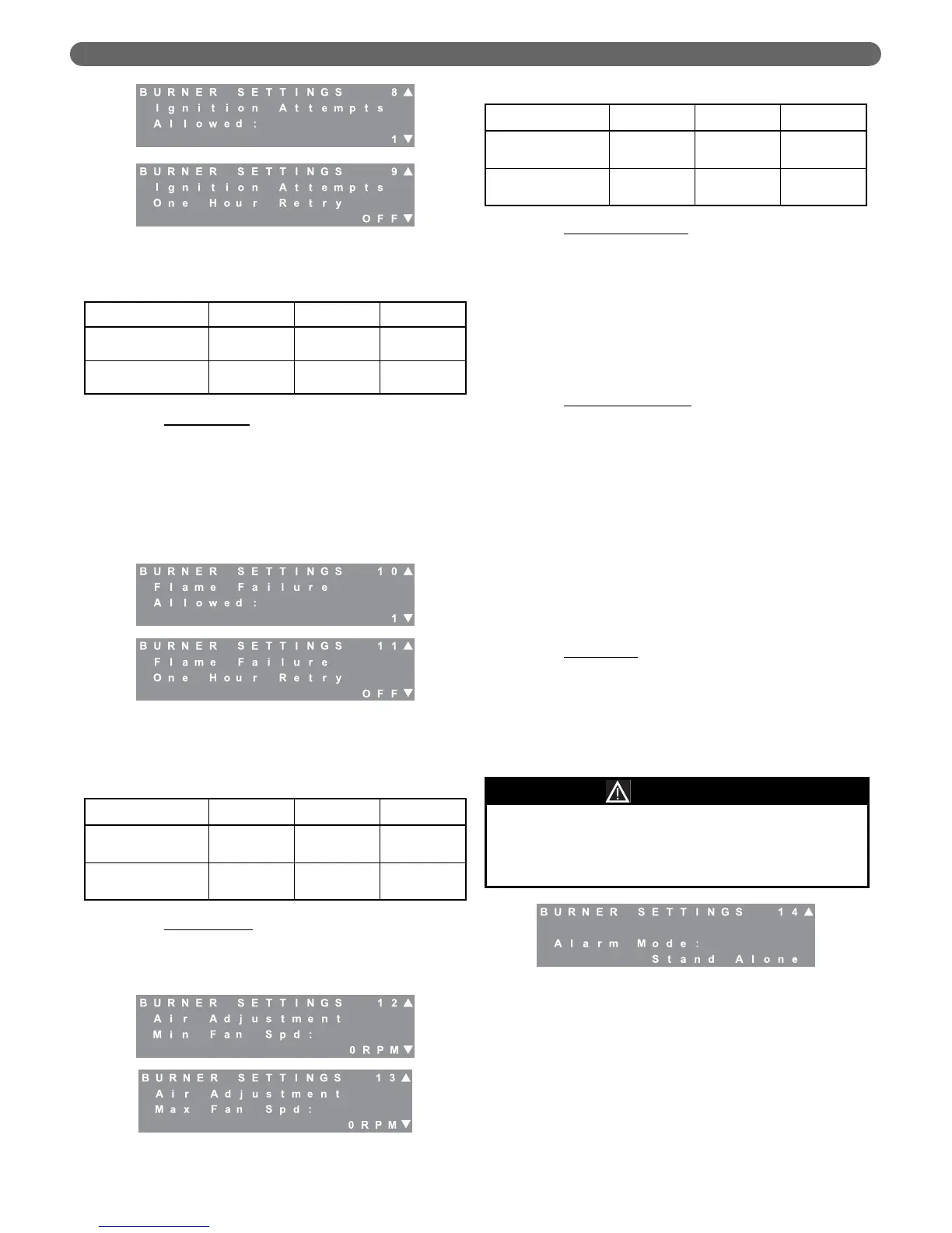
h. Flame Failures: The control is configured from the
factory to not allow the burner to recycle after a
flame failure. At installation, the control can be
configured to allow up to 2 retries after a flame
failure before locking out and requiring a manual
control reset. In addition, the control may be
configured to retry for ignition one hour after a
lockout without a manual reset. Check applicable
codes before changing these parameters.
i. Air Adjustment
: Screens #12 and #13 allow the
fan speed to be increased if required. The
following is an explanation of the conditions under
which these adjustments should be made.
j. Minimum Fan Speed
: The minimum fan speed
adjustment is intended to respond to potential
issues with the loss of flame due to pressure
fluctuations in the venting system. These concerns
may be due to wind gusts on sidewall vented
boilers or other sources of exhaust vent pressure
spikes. The minimum fan speed may be adjusted
in 30 RPM increments up to the minimum fan
speed + 540 RPM. This feature should only be
used to address nuisance flame failure or flapper
valve failure lockout errors.
k. Maximum Fan Speed
: The maximum fan speed
adjustment is intended to compensate for long
exhaust vent runs if the boiler fails to keep up with
the required load. Since the input rate may drop
off slightly under increased resistance due to long
exhaust vent installations, the boiler input may be
incrementally increased to compensate. This
adjustment should only be made if both of the
following conditions are met:
•
The boiler is not keeping up with the required
load.
•
The input rate has been determined to be below
the rated input by timing the gas supply meter.
If these conditions are not met, contact your
Peerless
®
Representative for assistance.
l. Alarm Mode
: The alarm mode allows the installing
contractor to set the menu to the mode
appropriate for the installation. The default setting
is “Stand Alone” in which the alarm contacts
(Terminals #31 & #32) simply close if an alarm
condition exists. The PFC-460 has no design
provisions that allow it to be included in a
common venting system.
4. Central Heating (CH) Settings
CH settings manage the boiler temperature and
circulators for the central heating load. Although the
menu items that follow are factory set, by default, to
values that can operate in any installation, they can
be adjusted to maximize the efficiency of this product.
The boiler can be configured to operate with a fixed
setpoint or using outdoor reset to vary the boiler
target temperature according to the load implied by
the outdoor temperature.
Figure 8.26: Burner Settings – Flame Failures
Allowed
Figure 8.25: Burner Settings – Ignition Attempts
Allowed
Table 8.14: Ignition Attempts Ranges & Defaults
Table 8.15: Flame Failures Allowed Ranges &
Defaults
Parameter Default Minimum Maximum
Ignition Attempts
Allowed
1 1 3
Ignition Attempts
1 Hr Retry
OFF OFF ON
Parameter Default Minimum Maximum
Flame Failure
Retries Allowed
0 0 2
Flame Failure
1 Hr Retry
OFF OFF ON
Figure 8.27: Burner Settings – Air Adjustment
Table 8.16: Air Adjustment Ranges & Defaults
Parameter Default Minimum Maximum
Air Adjustment
Min Fan Speed
0 rpm 0 rpm 540 rpm
Air Adjustment
Max Fan Speed
0 rpm 0 rpm 540 rpm
Figure 8.28: Burner Settings – Alarm Mode
DANGER
The PFC-460 cannot be vented into a common vent
with other boilers. There are no provisions to prevent
backflow through the heat exchanger. Severe personal
injury, death or major property damage will occur.
BOILER CONTROL: OPERATION