43
Note: Although stainless steel can withstand a
temperature higher than 230°F (110°C) the
temperature limit is set to this temperature since
the vent temperature should not exceed this
temperature unless there is a problem with the
heat exchanger.
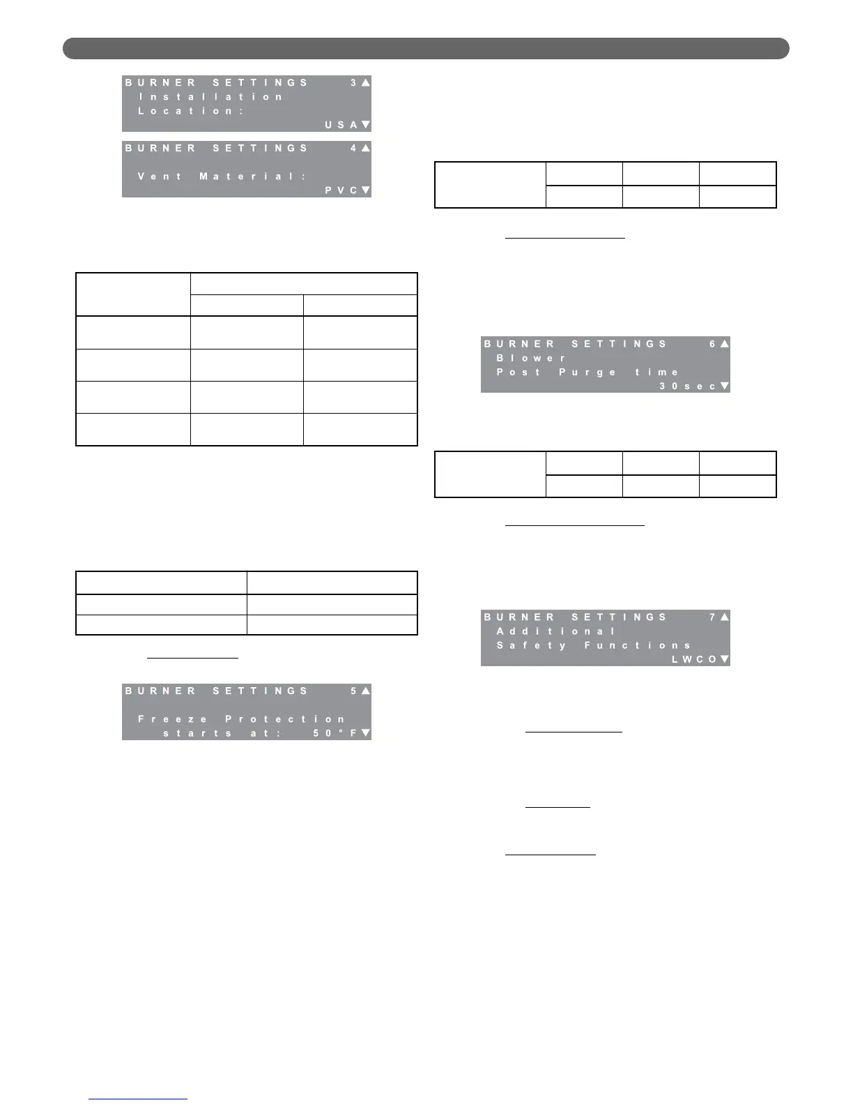
d. Freeze Protection
: Freeze protection is intended to
prevent freezing the central heating system.
•
First, the control activates pumps to distribute
heat uniformly through the system.
– If the boiler supply (header) temperature
drops below the value selected for “Freeze
Protection starts at:”, the General (boiler)
circulator is activated.
– If either of the boiler return sensors reports a
value below this temperature, the CH
circulator is started.
•
Next, if the return temperature drops more than
9° (5°C) below the “Freeze Protection starts at:”
value, the controls activates the burner at its
minimum rate.
– If a central heat demand is detected while the
burner is operating for Freeze Protection, the
burner will run normally to satisfy the demand.
– Finally, once the return temperature
increases to 9°F (5°C) above the chosen
value, the burner is switched off and the
pumps are deactivated.
e. Blower Postpurge Time
: The blower postpurge time
can be increased to address problems under extreme
conditions (long exhaust vent runs, high winds, etc.)
where the products of combustion are not fully
expelled from the venting system. This feature
should be used sparingly as it may lead to decreased
efficiency and higher fuel bills in certain situations.
f. Additional Safety Features
: The Boiler Control is
equipped with terminals for either a low water
cutoff or a flow switch. The low water cutoff is the
factory default and a factory supplied jumper is
installed. This jumper is to be removed if a low
water cutoff or flow switch is installed.
•
Low Water Cut Off: The installer can connect the
power supply wires for a probe-type low water
cutoff to terminal #19 (Hot) and #20 (Neutral)
in the main terminal box. The contacts should
be wired to terminals #9 and #10.
•
Flow Switch: If a flow switch is used, simply
wire the contacts to terminals #9 and #10 in
the main terminal box.
g. Ignition Attempts
: The control is configured from
the factory to not allow the burner to recycle after
a failed ignition attempt. At installation, the control
can be configured to allow up to 3 ignition
attempts before locking out and requiring a
manual reset. In addition, the control may be
configured to retry for ignition, one hour after
lockout without a manual reset. Check applicable
codes before changing these parameters.
Figure 8.23: Burner Settings – Blower Post Purge
Table 8.12: Freeze Protection Range & Default
Table 8.13: Blower Post Purge Range & Default
Table 8.10: Vent Temperature Limits
Vent Material
Location
U.S.A. Canada
PVC
190°F
(80°C)
149°F
(65°C)
CPVC
230°F
(110°C)
190°F
(80°C)
Polypropylene
(PPs)
230°F
(110°C)
230°F
(110°C)
Stainless Steel
230°F
(110°C)
230°F
(110°C)
Freeze Protection
Starts at
Default Minimum Maximum
50°F (10°C) 45°F (7°C) 56°F (13°C)
Blower Post
Purge Time
Default Minimum Maximum
30 sec 30 sec 120 sec
Table 8.11: Location & Vent Material Default
Figure 8.22: Burner Settings – Freeze Protection
Parameter Default
Location U.S.A.
Vent Material PVC
Figure 8.21: Burner Settings – Location & Vent
Material
Figure 8.24: Burner Settings – Additional Safety
Functions
BOILER CONTROL: OPERATION