50
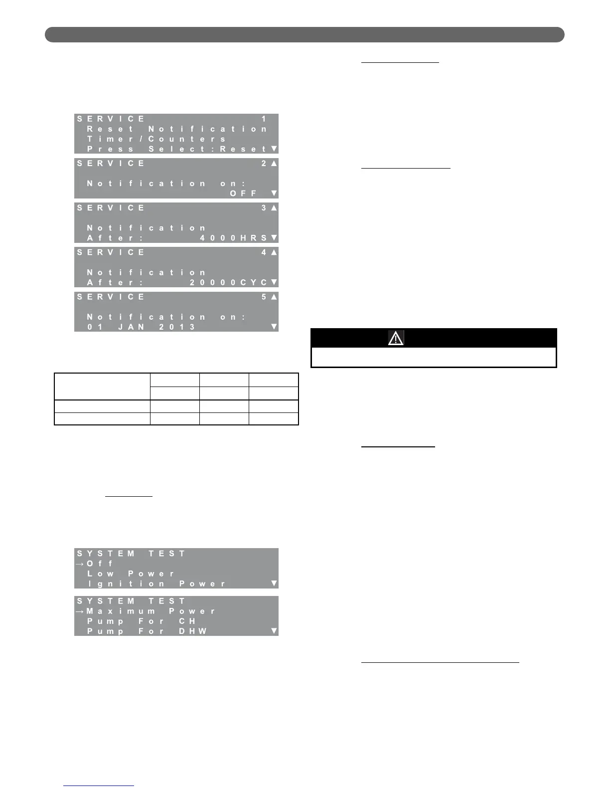
If desired, the installer can select a specific date for the
Service Notification. Simply press the “Select” key
when viewing the “Notification on:” date screen. Use
the “M” and “L” keys to set the value. Pressing
“Select” activates the next date parameter.
7. System Test
System Test settings allow the installer or service
person to operate each burner manually at it
maximum, minimum and ignition rates. The following
outlines the system test operation.
a. Burner Only
:
•
Eliminate all heat demands to the boiler by
disconnecting the CH thermostat from terminals
#1 & #2 and disconnecting the DHW sensor
or thermostat from terminals #5 & #6.
•
Use the “M” and “L” keys to position the
arrow at the desired power setting.
•
Press select to activate System Test. The
burner will ignite and then operate at the
selected input rate until “Off” is selected from
the System Test menu or for 1 hour. The
burner may cycle off on limit if the input rate
exceeds the heating load.
b. Pump For CH/DHW
:
•
This function can be used to check the function
of the CH and DHW circulating pump outputs.
•
While in “Standby”, choose the desired pump
output from the Installer Menu, System Test
screen on the display.
•
The pump terminals should be activated. If the
pumps don’t appear to be operating, check the
voltage on the pump output terminals.
c. Multiple Boiler Systems
:
•
These selections may also be used in a
multiple boiler, cascade system when testing a
dependent burner.
•
In multiple boiler systems, these pumps are to
be connected to the master boiler in the
cascade. Therefore, when a dependent boiler
is being tested, there will not likely be sufficient
heating load to run the boiler for very long.
•
In this case. Choose “Pump For CH” or
“Pump for DHW” from the System Test menu
on the display of the managing boiler in the
system before running the dependent boilers.
8. Sequence (Managing Burner Display Only)
Adjustments in the sequence menu affect the
sequence of burner operation. The first six parameters
will stop and start burners as follows:
a. On a call for heat (either CH or DHW) the 1st
burner will start. The 1st burner can be either the
managing or dependent burner based on the
Rotation Interval
chosen.
b. After the 1st burner is activated, the 2nd burner will
come on if all three of the following conditions are
met:
i. Supply Temperature < Target Temperature –
Start Burner Differential
ii. 1st Burner Input Rate > Next Burner Start
Rate
iii. Start Delay Time has elapsed (Time from
when both prior parameters are met)
c. The 2nd burner will be deactivated if the following
conditions are met:
i. Supply Temperature > Target Temperature +
Stop Burner Differential
ii. Both Burner Input Rates < Next Burner
Stop Rate
iii. Stop Delay Time has elapsed (Time from
when both prior parameters are met)
d. Calculated Setpoint Max Offset Up/Down
: The
target supply temperature of both burners are
adjusted if the system supply temperature is above
or below the targeted value. For example, if the
system supply target temperature is 150°F, each
burner will target this temperature. However, if
they approach their individual target temperature
before the system supply approaches its target, a
temperature offset is applied. This offset is
Figure 8.44: Service Notification
Table 8.31: Service Notification Ranges & Defaults
Notification On
Minimum Default Maximum
OFF OFF ON
Hours 0 4,000 8,000
Cycles 0 50,000 20,000
Figure 8.45: System Test Menu
The following features are non-functional for the PFC-460.
NOTICE
BOILER CONTROL: OPERATION