49
When this mode is chosen, the DHW Boiler
Temperature and the DHW Tank Temperature
setpoint values are available on the User Menu.
The control will modulate the burner input
based on feedback from the boiler supply
temperature sensor. Therefore, if the tank
temperature meets its setpoint before the boiler
supply is close to its setpoint, the boiler may
shut down while still in high fire. If this occurs
often, lowering the DHW boiler supply setpoint
will help to initiate modulation sooner.
Mode 1 can also decrease operating costs by
assuring that the boiler operates at its
minimum firing rate to address loads due only
to standby losses.
•
Mode 2, DHW Tank with Thermostat: This is
the default DHW mode and it operates with a
contact closure from a typical indirect tank
thermostat. In this mode, the control targets
the DHW boiler setpoint in the User Menu.
b. DHW Switch Time
: When the PUREFIRE
®
boiler
control is supervising the CH and DHW circulating
pumps, it operates with a limited DHW priority
strategy.
•
If there is a CH demand from the thermostat
when the DHW tank calls for heat, the control
will immediately switch from CH to satisfy the
DHW demand.
–
The control will continue to attempt to
satisfy the DHW load until the selected
switch time is reached.
–
Once the switch time is reached, the boiler
will switch back to the CH demand.
– If either the CH or DHW demand is satisfied,
the boiler will then focus on satisfying the
remaining load.
•
If there is a CH demand during a call for
DHW, the boiler will continue satisfying the
tank load until the switch time is reached.
– After that it will alternate loads at the end of
each switch time until one of the loads is
satisfied.
– Then again, it will focus on the remaining
call for heat.
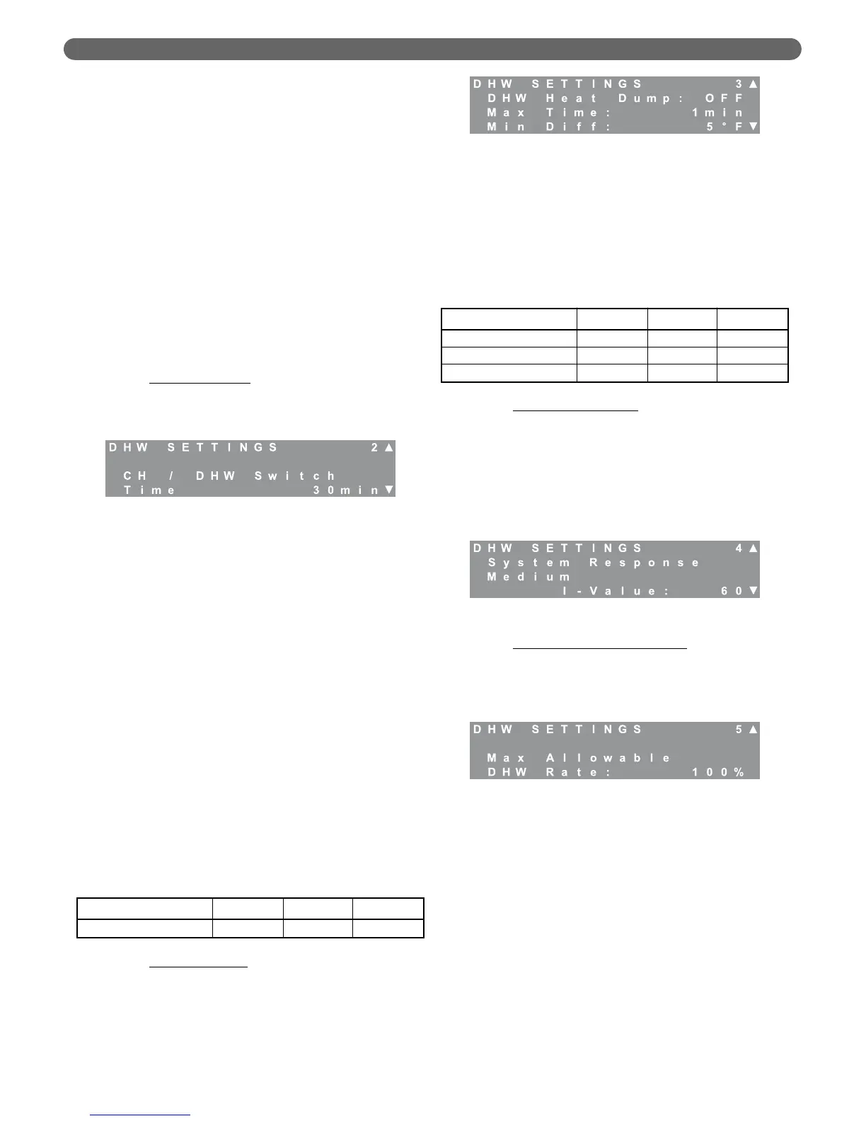
c. DHW Heat Dump
: Scientists at Brookhaven
National Laboratories have performed
experiments which suggest that diverting heat
from the boiler into an indirect storage tank at the
end of each cycle improves the overall efficiency
of the heating system. The heat dump function is
designed to take advantage of this principal.
•
At the end of a heating cycle, when the CH
demand is satisfied, the control switches off
the CH circulating pump and turns on the
DHW pump for the Max Time period.
•
If the temperature difference between the
supply and return of the boiler drops lower than
the Min Diff value, the pumps shut down.
d. System Response Time
: The system response time
works identically for DHW demands as it does for
CH demands. These values are designed to allow
independent modification of the response time for
CH and DHW loads. For small DHW loads, the I-
Value can be increased. For large DHW loads, this
value can be decreased. If the burner doesn’t
modulate when it satisfies a DHW load, this value
should be increased.
e. Maximum Allowable DHW Rate
: If the boiler is
sized primarily for a CH load that is significantly
higher than the DHW load, this value can be
decreased to limit the input rate of the boiler for
domestic hot water.
6. Service Notification
The P
UREFIRE
®
boiler control gives installers several
options to notify building owners when boiler service
should be performed. The first screen that appears, after
choosing Service Notification, is Reset Notifications.
Pressing select resets the hours and cycles to “0”.
The default for this optional feature is, “OFF”.
However, if it is enabled, the installer can choose the
number of hours, the number of cycles or the date
when, “SERVICE” appears on the LCD menu screens.
The following chart shows the range and default
values for the Service Notification feature.
Figure 8.40: CH Settings – DHW Priority Switch Time
Table 8.29: DHW Priority Switch Time Range &
Default
Parameter Minimum Default Maximum
CH/DHW Switch Time 5 minutes 30 minutes 60 minutes
Figure 8.41: DHW Settings – Heat Dump
Table 8.30: DHW Heat Dump Ranges & Defaults
Parameter Minimum Default Maximum
DHW Heat Dump OFF OFF ON
Maximum Time 0 minutes 1 minute 60 minutes
Minimum Difference 0°F (0°C) 5°F (3°C) 10°F (6°C)
Figure 8.42: DHW Settings – Response Time
Figure 8.43: DHW Settings – Maximum DHW Rate
BOILER CONTROL: OPERATION