48
r. Anti-Cycling Time: This function allows the
installer to set the minimum amount of time that
the boiler can be off on setpoint before recycling.
If the supply temperature drops by a value higher
than Tdiff, the boiler will ignore the minimum off
time and resume operation. If excessive cycling
occurs due to cycling of the thermostat or zone
relay, then the operation of these items should be
examined.
s. System Response Time
: To modify the reaction
time of the system for a CH demand, the I-value
parameter can be changed. The following chart
shows the range of values with descriptions of the
corresponding response speed.
Increase this value to reduce cycling in systems
with smaller zones. Decrease this value for a more
aggressive reaction to CH loads. This parameter
effects only the CH response time, a similar
parameter is available in the DHW Settings menu.
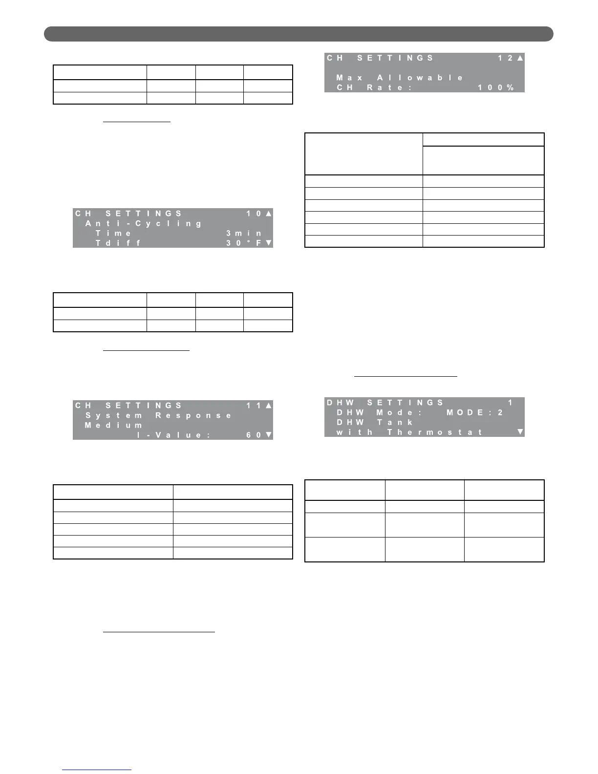
t. Maximum Allowable CH Rate
: If the boiler is sized
primarily for a DHW load that is significantly
higher than the CH load, this value can be
decreased to limit the input rate of the boiler for
central heating. The following chart shows the
effective input values for various modulation
percentages. As an example, if the DHW load is
460 MBH and the CH load is 310 MBH, set the
“Max Allowable CH Rate” to 60%.
5. Domestic Hot Water (DHW) Settings
DHW settings manage the boiler temperature and
circulators for the domestic water heating load. The
boiler can be configured to operate without a domestic
hot water load, with an indirect-fired hot water tank
which incorporates a conventional thermostat, or with
an indirect-fired hot water tank equipped with a water
tank temperature sensor (PB#54157). The configuration
using the optional tank temperature sensor allows the
control to maximize the efficiency of the system by
limiting the input rate to recover from standby losses.
a. Domestic Hot Water Modes
: This menu is used to
change the control response to calls for DHW.
•
Mode 0, No DHW: Mode 0 indicates that there
is no DHW load. The DHW pump outputs will
be deactivated and the control will not
respond to any signals at terminals #5 & #6.
•
Mode 1, DHW Tank with Sensor: Mode 1 is
used with a temperature sensor input from the
DHW tank. The optional sensor (PB #54157)
transmits the tank temperature to the control
which allows the control to determine the most
efficient boiler operation to address the heat
demand.
Table 8.24: Temperature Boost Ranges & Defaults
Parameter Minimum Default Maximum
Boost Temperature 0°F (0°C) 18°F (10°C) 36°F (20°C)
Boost Time 1 minute 20 minutes 60 minutes
Figure 8.36: CH Settings – Anti-Cycling
Table 8.25: Anti-Cycling Ranges & Defaults
Parameter Minimum Default Maximum
Anti-Cycling Time 0 minutes 3 minutes 15 minutes
Anti-Cycling Tdiff 20°F (11°C) 30°F (17°C) 40°F (22°C)
Figure 8.37: CH Settings – System Response
Table 8.26: System Response Range & Default
I-Value Response Time Description
15-20 Very Fast
25-40 Fast
45-80 (Default=60) Medium
85-110 Slow
115-120 Very Slow
Figure 8.38: CH Settings – Maximum CH Rate
Table 8.27: Maximum CH Rate Range & Default
% Modulation
Input Rate per Burner
PFC-460
Btu/hr
50% 230
60% 276
70% 322
80% 368
90% 414
100% 460
Figure 8.39: DHW Settings – DHW Modes
Table 8.28: DHW Modes
Mode Display
Input to Terminals
#5 & #6
0 No DHW None Required
1
DHW Tank
with Sensor
NTC Thermistor
Temperature Input
2
DHW Tank
with Thermostat
Dry Contacts from
DHW Thermostat
BOILER CONTROL: OPERATION