Cyclone Universal & Cyclone Universal FX - User Manual 20
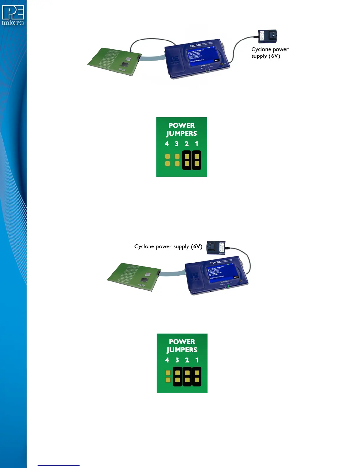
Figure 3-18: Via Cyclone Board Power and Power Out Jack of Cyclone
Jumpers 2 and 1 are installed, as shown in Figure 3-19.
Figure 3-19: Jumper Settings for Target Power Connection via Cyclone Board Power and Power Out
Jack of Cyclone
3.28.3 Setting C: Using Cyclone Board Power and Debug Connector TVCC
The target power supply is not needed. The TVCC pin of the Cyclone’s debug connector provides
the appropriate voltage for corresponding targets. The Power Out jack of the Cyclone’s connector
is not needed. Figure 3-20 shows the connections.
Figure 3-20: Via Cyclone Board Power and TVCC of Cyclone Debug Connector
Jumpers 3, 2, and 1are installed, as shown in Figure 3-21.
Figure 3-21: Jumper Settings for Target Power Connection via Cyclone Board Power and TVCC of
Cyclone Debug Connector
3.28.4 Setting D: Using Power IN Jack And Debug Connector TVCC Pin
A center positive power supply is connected to the Power IN Jack of the Cyclone. TVCC of the

 Loading...