3.4 Mechanical AHD
(Anti Hypoxic Device)
3.4.1 Introduction
The Mechanical AHD is housed within the
flowmeter module and comprises a gear
linkage between the oxygen control valve
and a needle valve in the nitrous oxide flow.
The system controls the relative flow rates of
oxygen and nitrous oxide.
A predetermined minimum oxygen
concentration of 30%
±3% in the oxygen /
nitrous oxide mixture is maintained over the
flow range to prevent delivery of a hypoxic
mixture.
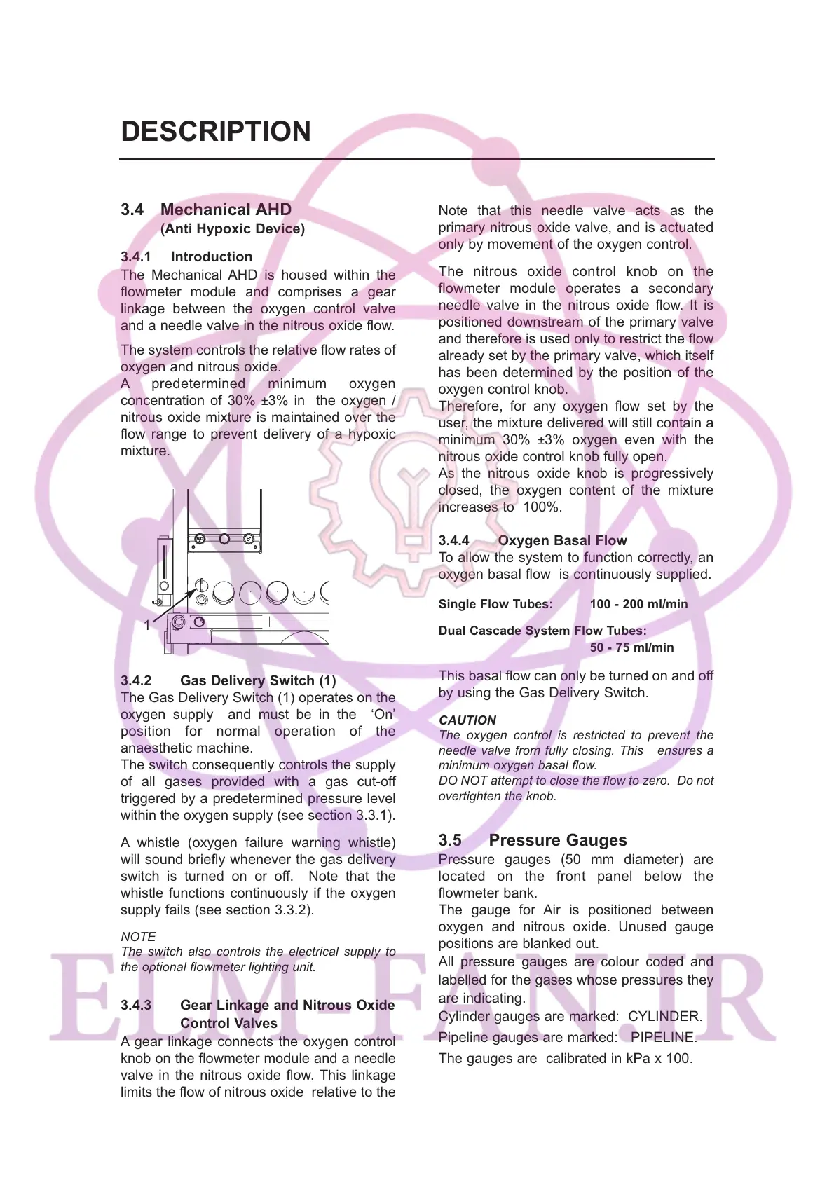
3.4.2 Gas Delivery Switch (1)
The Gas Delivery Switch (1) operates on the
oxygen supply and must be in the ‘On’
position for normal operation of the
anaesthetic machine.
The switch consequently controls the supply
of all gases provided with a gas cut-off
triggered by a predetermined pressure level
within the oxygen supply (see section 3.3.1).
A whistle (oxygen failure warning whistle)
will sound briefly whenever the gas delivery
switch is turned on or off. Note that the
whistle functions continuously if the oxygen
supply fails (see section 3.3.2).
NOTE
The switch also controls the electrical supply to
the optional flowmeter lighting unit.
3.4.3 Gear Linkage and Nitrous Oxide
Control Valves
A gear linkage connects the oxygen control
knob on the flowmeter module and a needle
valve in the nitrous oxide flow. This linkage
limits the flow of nitrous oxide relative to the
flow of oxygen set by the user.
Note that this needle valve acts as the
primary nitrous oxide valve, and is actuated
only by movement of the oxygen control.
The nitrous oxide control knob on the
flowmeter module operates a secondary
needle valve in the nitrous oxide flow. It is
positioned downstream of the primary valve
and therefore is used only to restrict the flow
already set by the primary valve, which itself
has been determined by the position of the
oxygen control knob.
Therefore, for any oxygen flow set by the
user, the mixture delivered will still contain a
minimum 30%
±3% oxygen even with the
nitrous oxide control knob fully open.
As the nitrous oxide knob is progressively
closed, the oxygen content of the mixture
increases to 100%.
3.4.4 Oxygen Basal Flow
To allow the system to function correctly, an
oxygen basal flow is continuously supplied.
Single Flow Tubes: 100 - 200 ml/min
Dual Cascade System Flow Tubes:
50 - 75 ml/min
This basal flow can only be turned on and off
by using the Gas Delivery Switch.
CAUTION
The oxygen control is restricted to prevent the
needle valve from fully closing. This ensures a
minimum oxygen basal flow.
DO NOT attempt to close the flow to zero. Do not
overtighten the knob.
3.5 Pressure Gauges
Pressure gauges (50 mm diameter) are
located on the front panel below the
flowmeter bank.
The gauge for Air is positioned between
oxygen and nitrous oxide. Unused gauge
positions are blanked out.
All pressure gauges are colour coded and
labelled for the gases whose pressures they
are indicating.
Cylinder gauges are marked: CYLINDER.
Pipeline gauges are marked: PIPELINE.
The gauges are calibrated in kPa x 100.
8
DESCRIPTION
1