3.1 General Construction
Frame
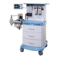
The machine has a cast aluminium base,
extruded aluminium uprights, with aluminium
and plastic panels.
Mobility
Four castors are fitted, with a brake on each
of the front castors. The castors are five
inches diameter.
A footrest is built into the front of the
machine and, to aid manoeuvrability, two
handles are provided.
Mounting posts and brackets
A mounting system is built into each side
upright, to allow the use of pole-mount
brackets, V-brackets, and ventilator
mounting brackets.
The pole mount upright can be used to
mount an A200SP Absorber assembly.
Work surfaces
The work surface has raised edges to retain
instruments, vials etc.
A pull-out writing tablet is mounted under the
work surface.
3.2 Gas Circuit
Gas Circuit Schematic
A gas circuit schematic is shown on the
following page.
Gas Supplies
A variety of cylinder and pipeline
combinations can be added to the basic
specification of oxygen and nitrous oxide
cylinder and pipeline supply.
For example, two extra gas cylinders
(choose from one additional oxygen, one
additional nitrous oxide, one air), and one
extra pipeline supply - Air.
Cylinder Yokes
The yokes are rear mounted and conform
with ISO standards for pin-index fitting.
To ensure that only cylinders of the
appropriate gas may be installed the yokes
are designed so that the retaining latch
cannot be closed unless the index pins are
fully engaged.
5
3. DESCRIPTION
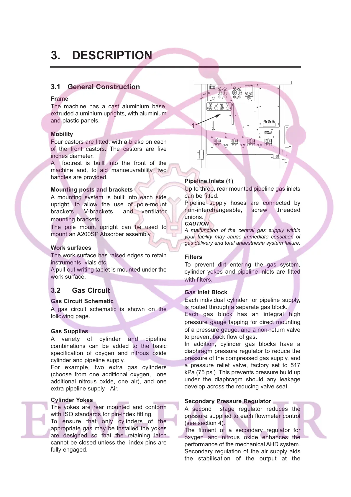
Pipeline Inlets (1)
Up to three, rear mounted pipeline gas inlets
can be fitted.
Pipeline supply hoses are connected by
non-interchangeable, screw threaded
unions.
CAUTION
A malfunction of the central gas supply within
your facility may cause immediate cessation of
gas delivery and total anaesthesia system failure.
Filters
To prevent dirt entering the gas system,
cylinder yokes and pipeline inlets are fitted
with filters.
Gas Inlet Block
Each individual cylinder or pipeline supply,
is routed through a separate gas block.
Each gas block has an integral high
pressure gauge tapping for direct mounting
of a pressure gauge, and a non-return valve
to prevent back flow of gas.
In addition, cylinder gas blocks have a
diaphragm pressure regulator to reduce the
pressure of the compressed gas supply, and
a pressure relief valve, factory set to 517
kPa (75 psi). This prevents pressure build up
under the diaphragm should any leakage
develop across the reducing valve seat.
Secondary Pressure Regulator
A second stage regulator reduces the
pressure supplied to each flowmeter control
(see section 4).
The fitment of a secondary regulator for
oxygen and nitrous oxide enhances the
performance of the mechanical AHD system.
Secondary regulation of the air supply aids
the stabilisation of the output at the
flowmeter.
1