3.6 Flowmeters and Controls
3.6.1 All models
The flowmeters, mounted behind the perspex
cover on the left hand side of the machine, are
length-indexed to prevent inadvertent, incorrect
installation.
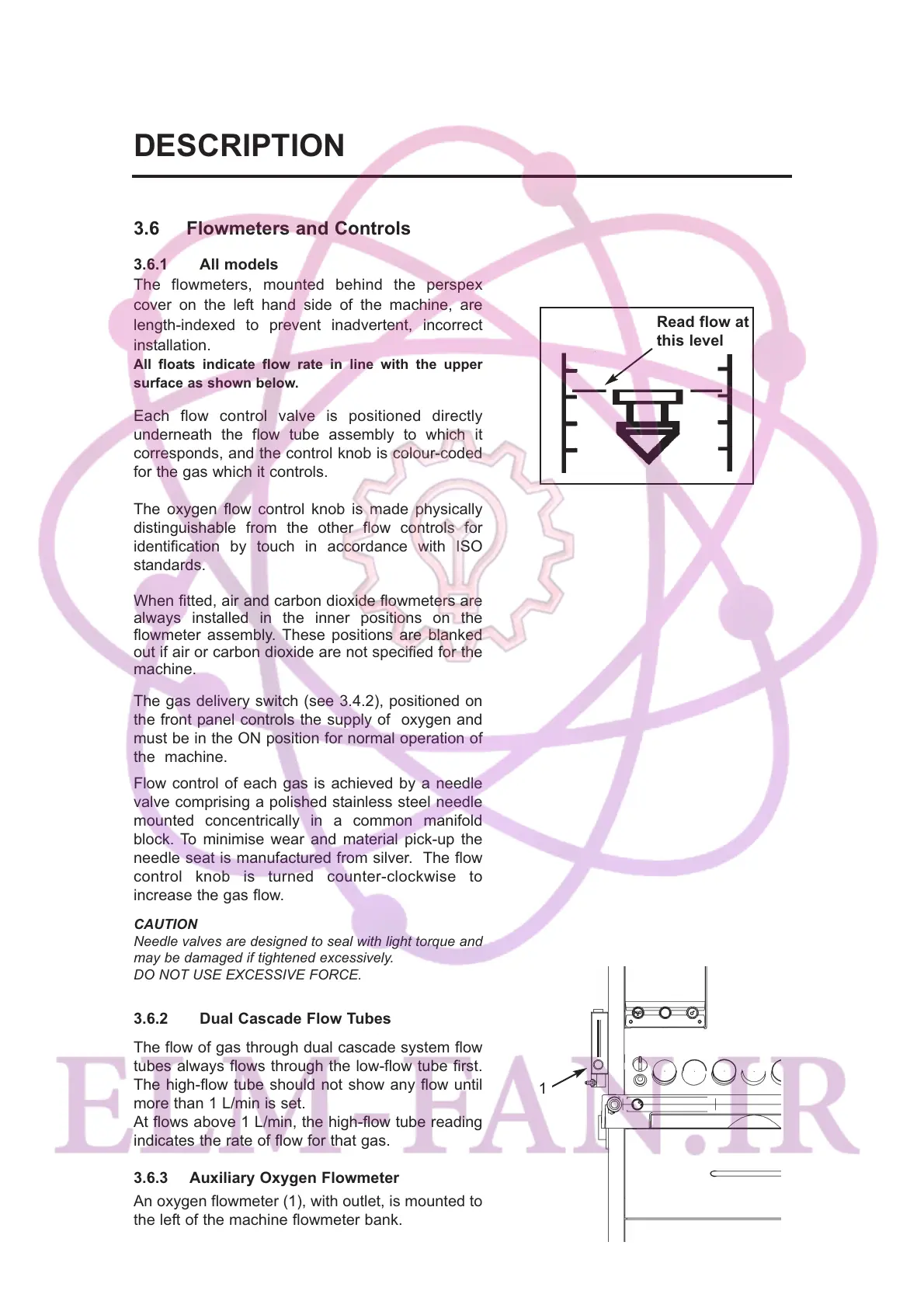
All floats indicate flow rate in line with the upper
surface as shown below.
Each flow control valve is positioned directly
underneath the flow tube assembly to which it
corresponds, and the control knob is colour-coded
for the gas which it controls.
The oxygen flow control knob is made physically
distinguishable from the other flow controls for
identification by touch in accordance with ISO
standards.
When fitted, air and carbon dioxide flowmeters are
always installed in the inner positions on the
flowmeter assembly. These positions are blanked
out if air or carbon dioxide are not specified for the
machine.
The gas delivery switch (see 3.4.2), positioned on
the front panel controls the supply of oxygen and
must be in the ON position for normal operation of
the machine.
Flow control of each gas is achieved by a needle
valve comprising a polished stainless steel needle
mounted concentrically in a common manifold
block. To minimise wear and material pick-up the
needle seat is manufactured from silver. The flow
control knob is turned counter-clockwise to
increase the gas flow.
CAUTION
Needle valves are designed to seal with light torque and
may be damaged if tightened excessively.
DO NOT USE EXCESSIVE FORCE.
3.6.2 Dual Cascade Flow Tubes
The flow of gas through dual cascade system flow
tubes always flows through the low-flow tube first.
The high-flow tube should not show any flow until
more than 1 L/min is set.
At flows above 1 L/min, the high-flow tube reading
indicates the rate of flow for that gas.
3.6.3 Auxiliary Oxygen Flowmeter
An oxygen flowmeter (1), with outlet, is mounted to
the left of the machine flowmeter bank.
9
DESCRIPTION
Read flow at
this level
1