System 450™ Series Modular Control Systems with Standard Control Modules Technical Bulletin
55
If the voltage is out of the specified range, check the sensor wiring for shorted or open circuits. Repair or replace
wiring as needed. If the wiring appears to be in good condition, replace the sensor and retest the voltage and
operation.
Repair and Ordering Information
Table 12 provides ordering information for the System 450 Series modules that can be used to build standard
control systems. See Technical Specifications
on page 63 for detailed product specifications for the control
modules listed in Table 12.
Table 14 through Table 26 provide ordering information for the System 450 compatible sensors and transducers.
For more information on installing System 450 compatible sensors and transducers, see Related Documentation
on page 61 for additional information on the modules listed in Table 12.
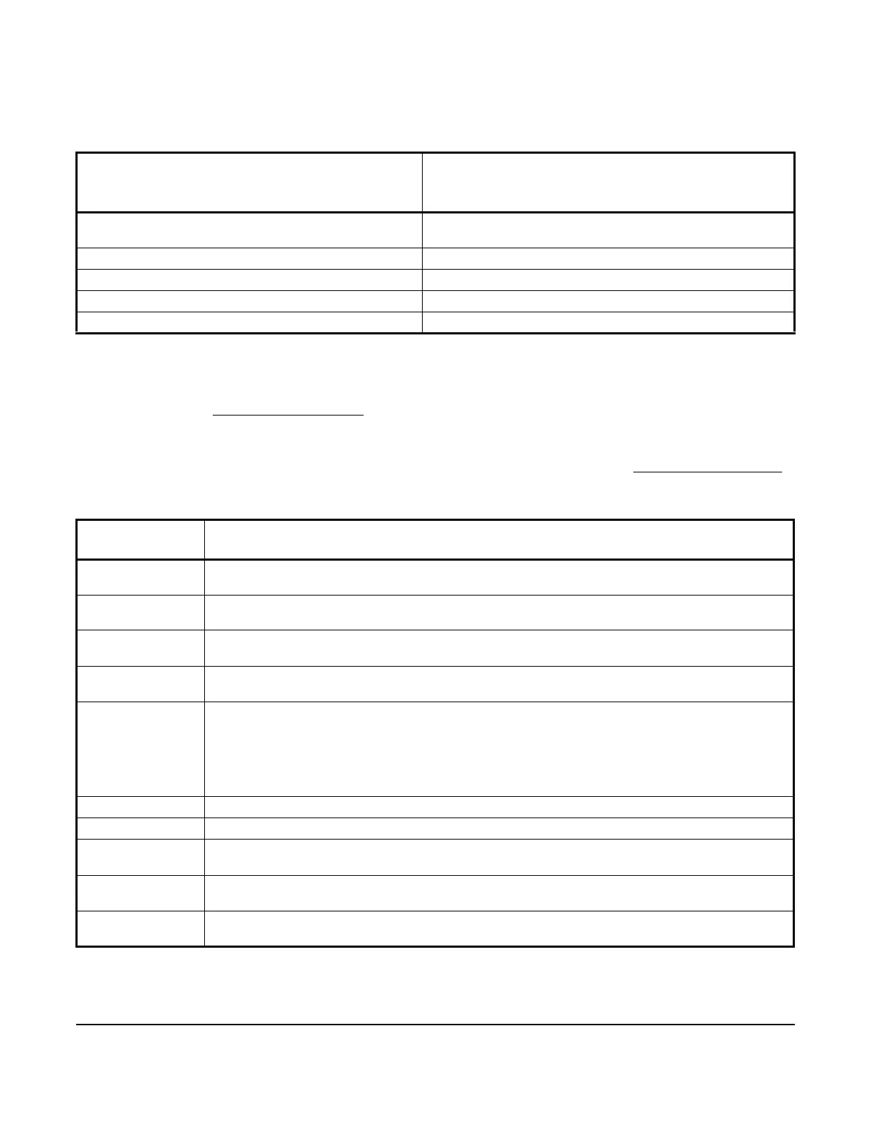
Table 11: Specified Voltage Ranges between Sensor Terminals
Connected Sensor Specified Voltage Range
Measured between a Sensor Terminal (Sn1, Sn2, or
Sn3) and a Common Terminal (C)
A99B Series and TE-6xxx Series Nickel (1,000 ohms at
70F) Temperature Sensors
0.49 to 1.43 VDC
HE-67xx Humidity Sensor 0 to 5.0 VDC
DPT2650 Low-Pressure Differential Sensor 0 to 5.0 VDC
P499 Series Electronic Pressure Transducer 0.5 to 4.5 VDC
P598 Series Electronic Pressure Transducer 0.5 to 4.5 VDC
Table 12: System 450 Modules and Accessories Ordering Information
Product Code
Number
Product Description
C450CBN-4C Standard Control Module with LCD, Four-Button Touchpad UI, and Relay Output; provides one relay
output (SPDT line-voltage relay) for SPDT control.
C450CCN-4C Standard Control Module with LCD, Four-Button Touchpad UI, and Relay Output; provides two relay
outputs (SPDT line-voltage relays) for SPDT control.
C450CPN-4C Standard Control Module with LCD, Four-Button Touchpad UI, and Analog Output; provides one analog
output (0–10 VDC or 4–20 mA self-selecting signal) for proportional control.
C450CQN-4C Standard Control Module with LCD and Four-Button Touchpad UI, and Analog Output; provides two
analog outputs (0–10 VDC or 4–20 mA self-selecting signals) for proportional control.
C450CPW-100C Hybrid Analog Output Control Module with LCD, Four-Button Touchpad UI, Hybrid Analog Output and
Optional High Input Signal Select; provides one hybrid analog output and optional high input signal
select primarily used for variable-speed EC motor speed control.
Only Analog Output 1 (OUTA1) can be configured as a hybrid analog output and/or use the High Input
Signal Selection feature. These features are not available for any of the other outputs in a System 450
control system that uses the C450CPW-100C as the control module.
C450SBN-3C Relay Output Expansion Module; provides one SPDT line-voltage relay output.
C450SCN-3C Relay Output Expansion Module; provides two SPDT line-voltage relay outputs.
C450SPN-1C Analog Output Expansion Module; provides one analog output (0–10 VDC or 4–20 mA self-selecting
signal) for proportional control.
C450SQN-1C Analog Output Expansion Module; provides two analog outputs (0–10 VDC or 4–20 mA self-selecting
signals) for proportional control.
C450YNN-1C Power Module; provides 24 V to System 450 Module Assembly; 120 VAC or 240 VAC supply power
input terminals.
 Loading...

