System 450™ Series Modular Control Systems with Standard Control Modules Technical Bulletin
7
The System 450 System Status screens display the status of each output in the control system (in addition to the
sensor status screens). A relay output status is displayed as On or OFF. An analog output status is displayed as a
percentage of the total output signal strength, 0 to 100 (%). The analog output status screens also display an icon
that indicates the control action of the analog output. See Direct and Reverse Control Actions for Analog Outputs
on page 18 for more information.
Figure 3 illustrates the System 450 UI navigation paths, parameter designations, and values for the control system
example (shown in Figure 2) using a System 450 standard control module. Figure 3 shows the Main screens, the
Sensor Status screens, the System Status screens, the System Setup screens, and the Output Setup screens for
examples of the System 450 standard control application.
Expansion Modules, Module Assemblies, and Outputs
System 450 expansion modules provide additional outputs to expand your control systems and meet your specific
application requirements.
A System 450 control system provides up to ten outputs, which can be any combination of relay and analog
outputs. Expansion modules are available with one or two relay outputs, or with one or two analog outputs. See
Table 12 on page 55 for information on the System 450 modules that can be used in a control system.
Module Assemblies, Output Types, and Output Numbers
You can easily plug System 450 modules together using the 6-pin connectors located on the sides of the modules’
housings and mount these module assemblies on standard 35 mm DIN rail (recommended) or directly to a hard,
even surface. See Mounting
on page 35 for more information.
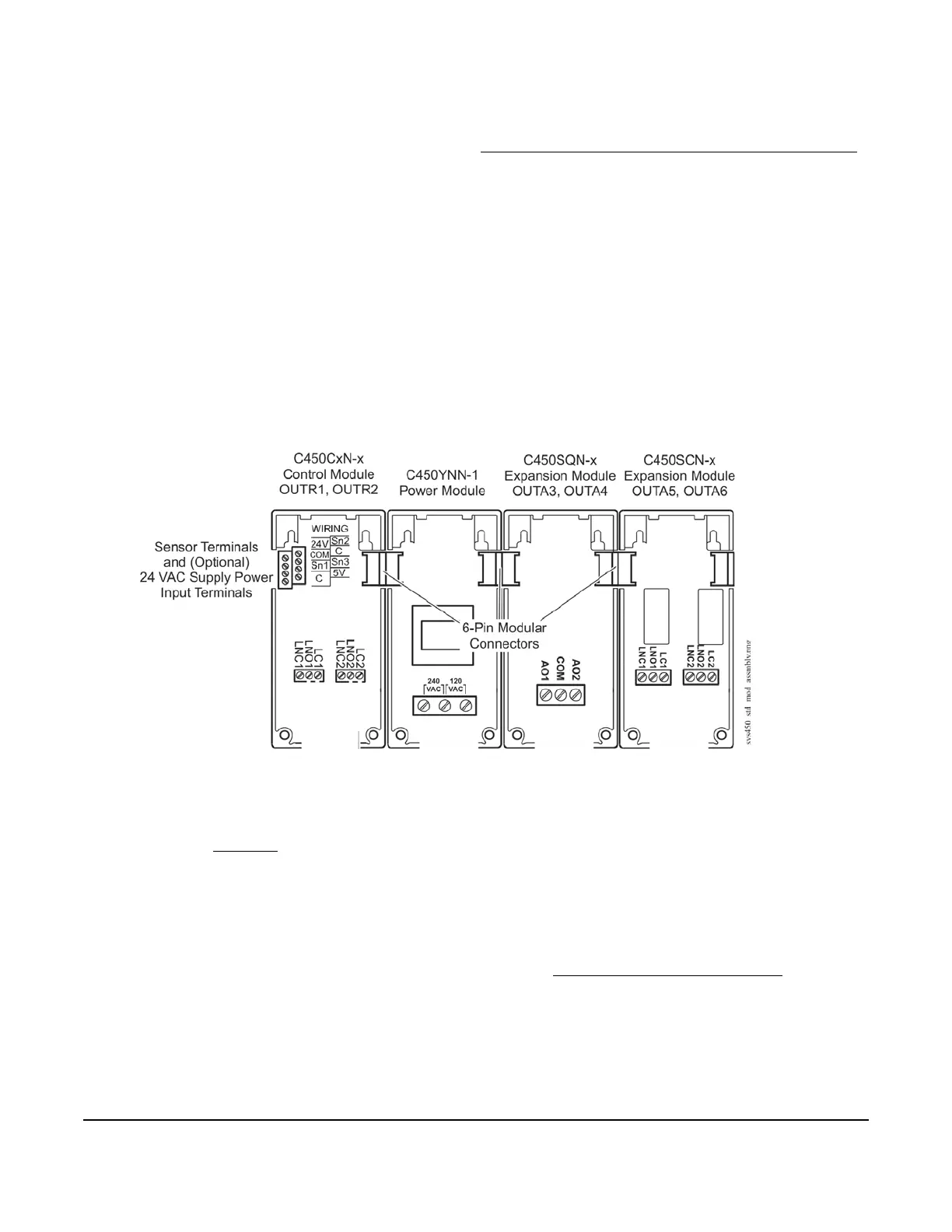
Figure 2 shows a System 450 module assembly example, the module positions, the output types, and the
automatically assigned output numbers used in the System Setup screens in the control module UI.
The control module is always mounted on the left side of the module assembly. If a System 450 power module is
used, the power module is always plugged into the right side of the control module. If expansion modules are used,
they can be plugged into the assembly in any order on the right side of the power module (or the right side the
control module, if a power module is not used in the assembly). See Assembling System 450 Modules
on page 35
for more information.
Each time a System 450 module assembly is powered on, the control module polls all of the modules to identify
output type (relay or analog) and then assigns an output number (1 to 9 and 0 = 10) to each output, starting with
the first output of the control module, and then polling each expansion module connected to the right. Output
numbers are displayed on the control module LCD to identify the output you are viewing as you navigate the
system status and setup screens in the System 450 UI (Figure 3).
Figure 2: System 450 Module Assembly Example Showing Standard Control Module and
Expansion Module Positions, Output Positions, and Output Numbers
 Loading...

