System 450™ Series Modular Control Systems with Standard Control Modules Technical Bulletin
54
7. Use the slower of the two measured response times and the following table to determine which integration
constant (I-C setting) to set on the control and test first.
8. Set the integration constant to the determined I-C setting. Operate and observe the controlled system at a
variety of load conditions to determine if the system is stable at the determined I-C setting over the entire
output range of the controlled system.
Troubleshooting System 450 Control Systems
System 450 control modules display error messages on the LCD when the module detects a sensor, sensor wiring,
sensor power, or power supply failure.
Table 10 shows the System 450 error messages that may be displayed, and provides possible causes for the error
messages and the solutions for remedying the errors.
Specified Voltage Ranges for Sensors
Table 11 provides the specified operating voltage range for System 450 sensors. To determine if a sensor is
operating in the specified range, measure the voltage between the sensor’s terminal connections at the
System 450 control module (the Sn1, Sn2, or Sn3 terminal and one of the C terminals).
Table 9: Response Times, Reset Rates, and Integration Constants
Slowest Measured
Response Time for Control
Point Shift
Select This Integration
Constant (I-C) Value for the
Analog Output
Estimated Total Reset Rate for Integration
Constant
N/A 0 No reset rate
10 to 15 minutes 1 1 hour (3,600 seconds)
6 to 10 minutes 2 30 minutes (1,800 seconds)
3 to 6 minutes 3 15 minutes (900 seconds)
1 to 3 minutes 4 5 minutes (300 seconds)
30 to 60 seconds 5 2 minutes (120 seconds)
10 to 30 seconds 6 1 minute (60 seconds)
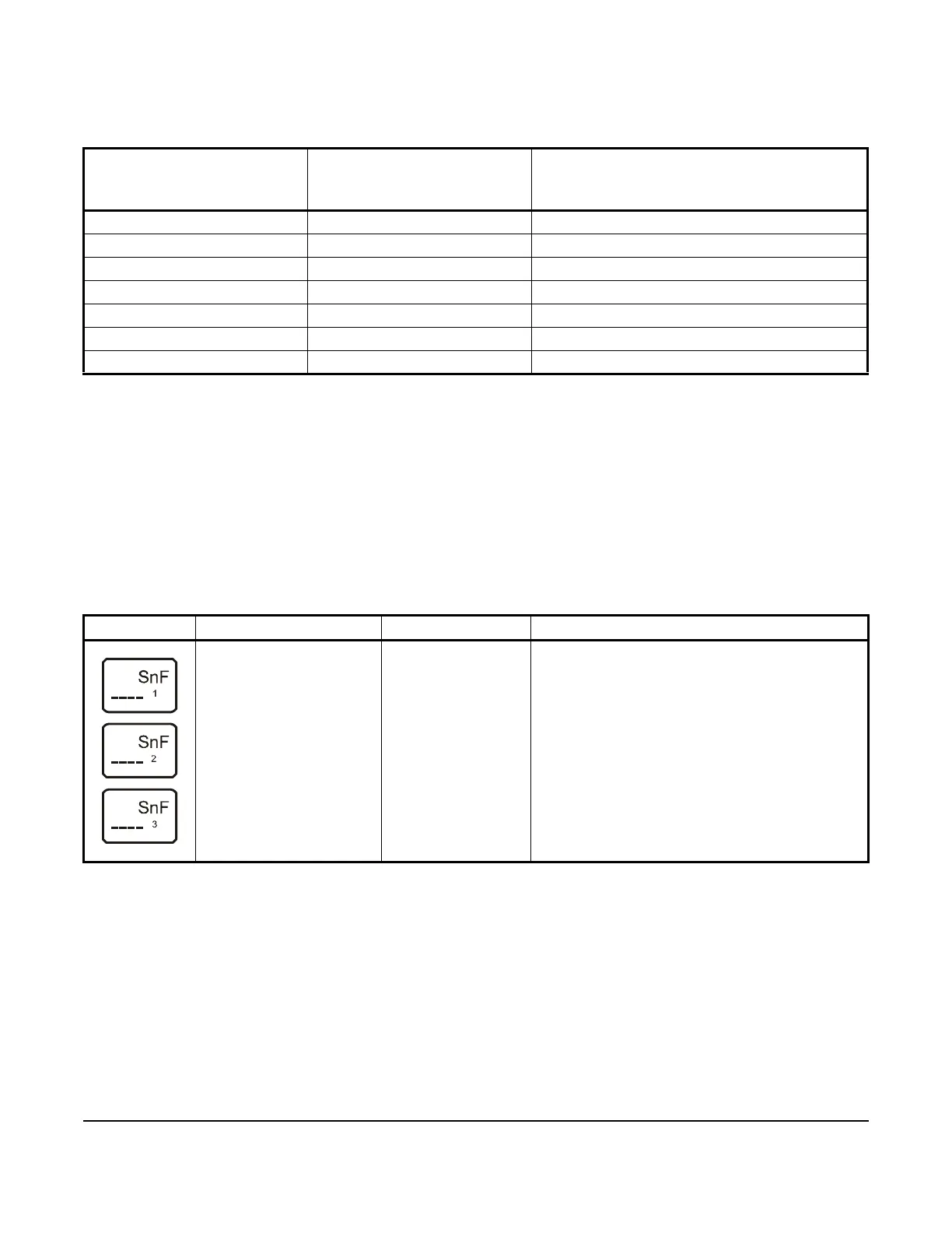
Table 10: System 450 Control System LCD Error Messages
Error Screen Problem/Symptom Possible Cause Solution
Sensor failure is detected
and < SNF > is displayed
(instead of a value).
Outputs that reference
the failed sensor are
operating in the Sensor
Failure Modes selected
for the Output at setup.
Sensor, sensor
wiring, or sensor
connections may
have failed to open or
close.
Check and the verify integrity of sensor wiring and
connections. Measure the voltage between the
sensor terminal (Sn1, Sn2, or Sn3) and the low-
voltage common (C) terminal (with the sensor
connected). See Table 11 for the sensor’s expected
voltage range. If the sensor wiring and sensor
connections are good, replace the sensor and
recheck the voltage.
 Loading...

