System 450™ Series Modular Control Systems with Standard Control Modules Technical Bulletin
51
Note: Only Analog Output 1 (OUTA
1
) is capable of generating the Pulse-AO. Additional AO expansion
modules provide a standard 0 to 10 VDC or 4 to 20 mA output signal.
2. In the Pulse Output Level Selection Screen (LEV
x
), set the Pulse Output Level to a (percent) value that is
higher than required for the EC Motor to rotate. If the motor requires a minimum speed reference of 2 VDC
before it rotates, set the Pulse Level higher than 2.5 VDC (25%). Press or to select this Output’s Pulse
Output Level value. Press to save the Pulse Output Level value and go to the Pulse Period Selection
Screen (PER
x
).
Note: Screen example shows the Pulse Output Level set to 25%. Range is 0 to 100%. Set the Pulse Output
Level to 0% to disable the pulse output. Set the Pulse Output Level to 100% to use the pulse output
over the entire 0 to 10 V output range.
3. In the Pulse Period Selection Screen (PER
x
), press or to select this output’s Pulse Period value. Press
to save your Pulse Period value selection and go to the Pulse Region Hybrid AO Setup Start Screen
(PULS
x
).
Screen example shows the Pulse Period set for 2 seconds. Range is 1 to 30 seconds.
Setting Up Outputs That Reference a P 110 Sensor
The P 110 Sensor Type can monitor negative pressure down to 20 inHg (-10 psi). When referencing a P 110
sensor, System 450 displays negative pressure values in inHg on the Main and System Status screens. But when
you set up an output that references a P 110 sensor and the setup value is a negative pressure value, you must
select the pressure value in negative psi (not inHg).
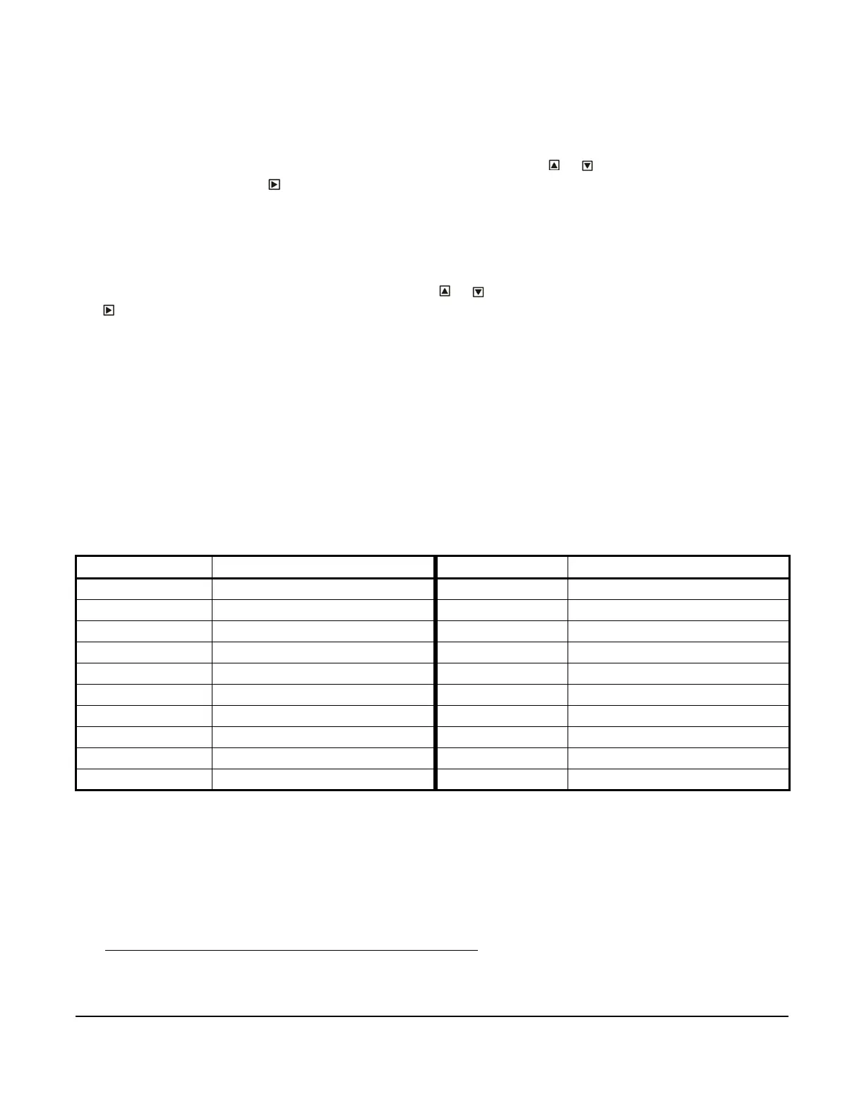
Use Table 8 to determine the negative PSI setup value that corresponds to your inHg target value. For example, if
you want a relay output to go off when the sensed pressure reaches 7 inHg, you select the value -3.5 (psi) in the
output’s Relay OFF Selection screen.
When an output is set up for Differential Control and references the P 110 Sensor Type (Sn-1 and Sn-2 are both P
110 Sensor Type), the sensed negative pressure values displayed in the Main screen for differential pressure
status (dIFP) are displayed as negative psi values, not inHg values.
Determining the Integration Constant for an Analog Output
The default Integration Constant (I-C) setting for analog outputs is 0 (zero) or no integration constant. An I-C setting
of 0 provides a proportional-only analog signal. Most applications do not require you to change this default setting.
See Proportional Plus Integral Control and Integration Constants
on page 20 for more information.
If you want to apply proportional plus integral to a control loop in your controlled system, here are two methods of
determining the best I-C setting for the analog output that controls the loop.
Table 8: inHg Target Values and Equivalent psi Setup Values
inHg Value psi Setup Value inHg Value psi Setup Value
1 -0.5 11 -5.5
2 -1.0 12 -6.0
3 -1.5 13 -6.5
4 -2.0 14 -7.0
5 -2.5 15 -7.5
6 -3.0 16 -8.0
7 -3.5 17 -8.5
8 -4.0 18 -9.0
9 -4.5 19 -9.5
10 -5.0 20 -10.0
 Loading...

