System 450™ Series Modular Control Systems with Standard Control Modules Technical Bulletin
5
• High Input Signal Selection allows you to monitor a condition with two or three identical sensors at different
locations in your controlled system and control system outputs according to the highest condition value
monitored by the sensors. See High Input Signal Selection
on page 23 for more information.
• Differential Control allows you to monitor and control a condition differential in a controlled system; for
example, the water pressure drop across an in-line water filter. See Differential Control
on page 24 for more
information.
• Hybrid Analog Output Control (C450CPW-100) enables an analog VDC output to transition to a pulse output
at low signal levels, providing more efficient low-speed control of Electronically Commutated (EC) motors in
condenser fan applications. See Hybrid Analog Output
on page 9 for more information.
• Output Update Rate allows you to select the rate at which an analog output updates the output signal to the
controlled equipment. See Analog Output Update Rate
on page 21 for more information.
• Output Signal Deadband allows you to create a deadband for the analog output signal within which the output
signal strength remains constant. See Analog Output Deadband
on page 22 for more information.
• Four Time Control Parameters allow you to set up the relay outputs with On or Off time delays and minimum
On or Off times. See Relay On and Off Duration Control
on page 15 for more information.
• On/Off Delay allows you to configure an on delay (the time between a setpoint trip and the energizing of a
relay) and an off delay (the time between a setpoint trip and the de-energizing of a relay).
Note: Only the C450CPW-100 model provides a hybrid analog output for direct control of EC motors. See Hybrid
Analog Output on page 9 for more information.
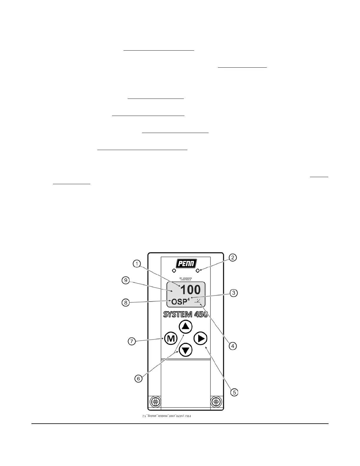
Control Module and User Interface
Each System 450 standard control system requires a single control module. System 450 Control modules have
an LCD that enables you to set up and monitor your control system, along with a four-button touchpad for
navigating the control system status and setup screens, and setting up the system parameters. Figure 1 shows
a control module and Table 1 describes the various features of the System 450 control system UI for control
modules.
Figure 1: System 450 Control Module Output Analog LEDs, LCD, Four-Button Touchpad User Interface
 Loading...

