System 450™ Series Modular Control Systems with Standard Control Modules Technical Bulletin
6
Standard System 450 control modules are available with one or two relay outputs or with one or two analog outputs
and the standard System 450 firmware. See Table 12 on page 55 for model descriptions and System 450 Control
Systems with Standard Control Modules on page 4 for more information.
The System 450 control module with hybrid analog output has a single analog output that can be configured as a
hybrid analog output to optimize and extend the controlled speed range of variable speed EC motors. See Hybrid
Analog Output on page 9 for more information.
All System 450 control modules can control both relay outputs and analog outputs, regardless of the type of
outputs that the control module has on-board. You set up all of the sensors and all of the outputs (relay and
analog), including the expansion module outputs, in the control module UI. A standard control module can also be
configured as a simple stand-alone control system when your application requires only one or two relay outputs, or
one or two analog outputs.
During normal operation, the LCD displays the Main System 450 screens (Sensor Status screens), which
automatically scroll through and display the status of the hard-wire and functional sensors in your control system.
You can also view the status of all the outputs in your control system and access the System Setup screens from
the Main screens in the System 450 UI. See Setting up a System 450 Control System
on page 40 for more
information.
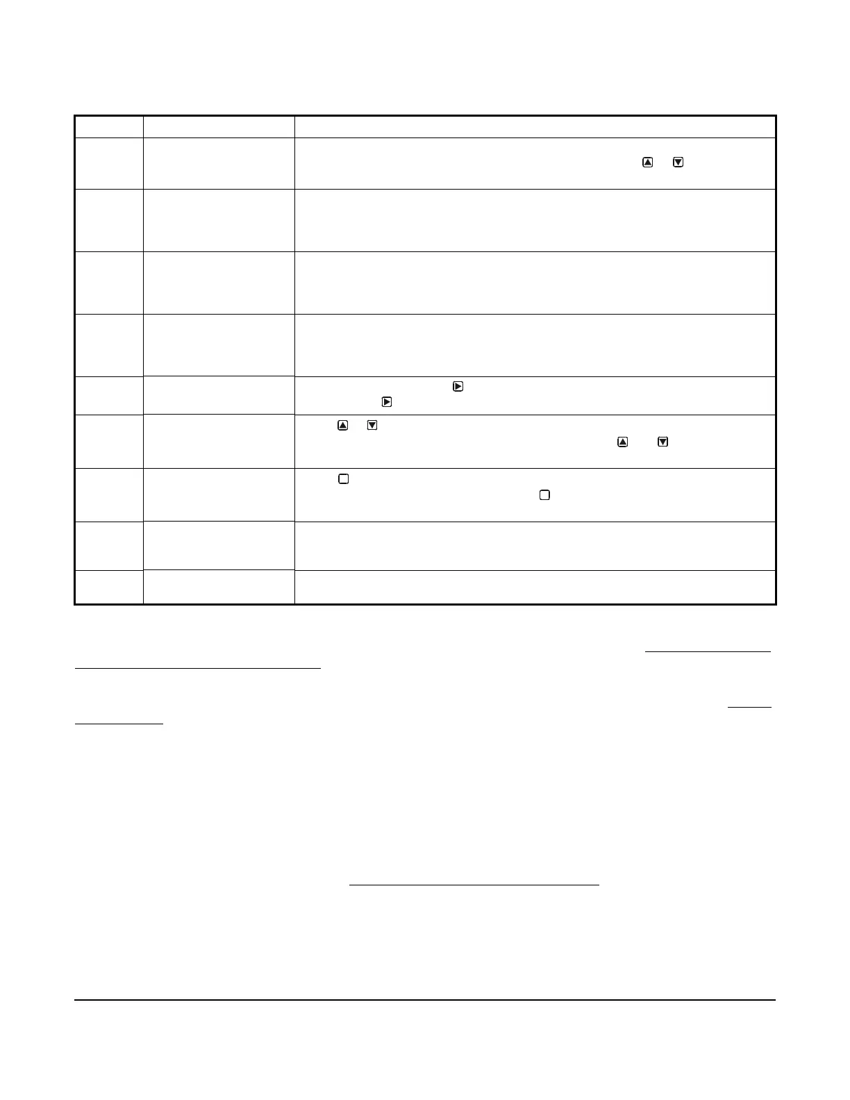
Table 1: System 450 Control Module Output Analog LEDs, LCD, Four-Button Touchpad User Interface
Callout Feature Description
1 Status or Setup Value Displays the current input status, output status or setup parameter value for the
displayed input sensor, output and/or setup parameter. Press or to select a
different parameter value when the value is flashing. (Here, 100 = 100%.)
2 LED Green LEDs on the Control Module and Expansion Modules indicate if the
associated relay or analog output is on or off. If the analog output is partially on
(between 0–10V), the LED blinks. The higher the output signal strength, the longer
the LED is on.
3 Output Number Displays a numerical value that identifies the output associated with the status or
setup value shown on the screen. Output numbers are automatically determined by
the outputs' physical positions (left to right) in the module assembly.
(Here, 4 = Output 4.)
4 Control Ramp Icon Displays whether an analog output (only) is set as direct-acting or reverse-acting,
and whether the output signal strength is at minimum or maximum when the sensed
property is at Setpoint. The control ramp icon displayed is determined by the output's
SP, EP, OSP, and OEP setup values.
5 Next Button
In the Main screens, press
to scroll through the system status screens. In a setup
screen, press
to save the (flashing) setup value and go to the next setup screen.
6 Up and Down Buttons
Press or to select a different value for any flashing value in the setup value field.
In the Main (sensor status) screens, press and hold both and for 5 seconds to
access the setup Start screens.
7 Menu Button
Press to move through the sensor and output setup start screens. When moving
through the status or setup screens, press to return to the status start screen or
setup start screen.
8 Status or Setup Identifier Displays the unit of measurement, output, sensor number, or setup parameter for the
displayed status or setup value. (Here, the setup identifier OSP represents % output
signal strength at setpoint).
9 LCD Backlit LCD screen. The LCD brightness is adjustable. During normal operation, the
LCD displays the Main screens.
M
M
 Loading...

