System 450™ Series Modular Control Systems with Standard Control Modules Technical Bulletin
50
6. In the Select Output Signal Strength at End Point (OEP
x
) screen, press or to select the value in
percent of the output signal strength (0 to 100%), corresponding to the highest output capacity, when the
sensor is at the End Point (EP
x
). Press to save the displayed OEP value and go to the next screen.
7. In the Select Integration Constant (I-C
x
) screen, press or to select the integration constant value for the
analog output. (See Determining the Integration Constant for an Analog Output
for more information.) Press
to save the displayed I-C value and go to the next screen.
8. In the Select Output Signal Update Rate (UP-R
x
) screen, press or to select the output update rate
value. One (second) is the default value. You can select a value between 1 and 240 (seconds). (See Analog
Output Update Limiters on page 21 for more information.) Press to save the output update rate value and go
to the next screen.
9. In the Select Output Signal Deadband (bNd
x
) screen, press or to select the output deadband value as
a percentage of the total output signal range. Zero (percent) is the default value. You can select a value
between 0 and 50 (percent). (See Analog Output Deadband
on page 22 for more information.) Press to
save the output deadband value and go to the next screen.
10. In the Select Sensor Failure Mode (SNF
x
) screen, press or to select whether the analog output signal is
to be set to its ON or OFF value when a failure of the referenced sensor is detected. (When sensor that is
referenced by analog output fails, the ON value sets the output to the OEP value and the OFF value sets the
output to the OSP value.) Press to save the displayed SNF value and go to the next screen.
11. In the Edit Sensor (SENS
x
) screen, you can change the hard-wired or functional sensor that the output
currently references:
• If the displayed sensor (Sn-1, Sn-2, Sn-3, Sn-d, HI-2, or HI-3) is the correct sensor for the output relay, the
output setup is complete. Press to go to the Analog Output Setup Start screen.
• If the displayed sensor (Sn-1, Sn-2, Sn-3, Sn-d, HI-2, or HI-3) is not the correct sensor for the output relay,
press or to select the correct sensor. Press to save the new sensor selection and go to the Analog
Setpoint Value screen. Repeat Step 3 through Step 10 for the new sensor.
12. When you complete setting up the analog output, press to return to the Analog Output Setup Start
(OUTA
x
) screen.
The analog output is set up and saved in the control module.
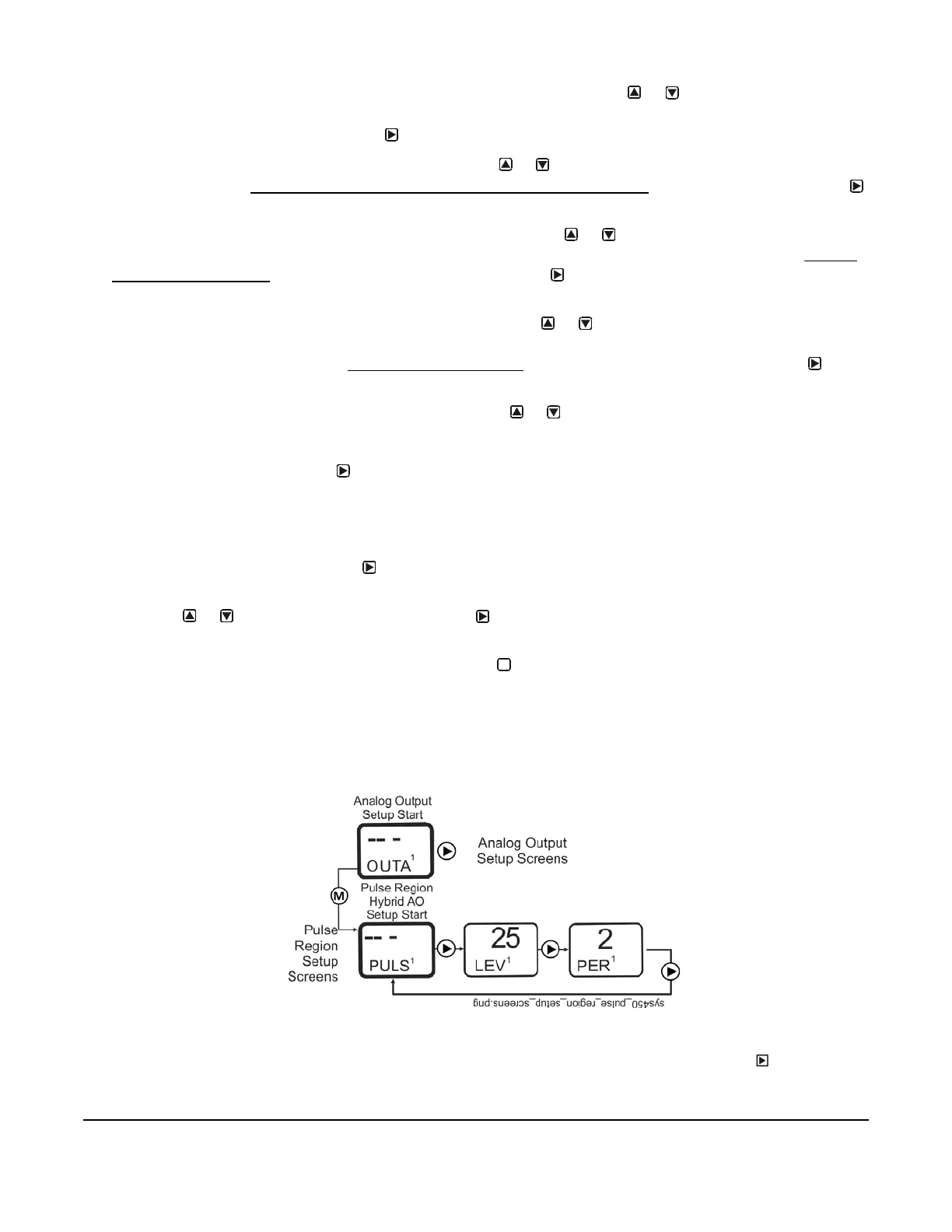
Setting up a Pulse Region Hybrid Analog Output
To set up the Pulse Region of a hybrid analog output for Output 1 on a C450CPW-100 control module:
1. From the Pulse Region Hybrid AO Setup Start Screen (PULS
x
) for Analog Output 1, press to go to the
output’s Pulse Output Level Selection Screen (LEV
x
).
M
Figure 30: Pulse Region Hybrid AO Setup Start Screen
 Loading...

