System 450™ Series Modular Control Systems with Standard Control Modules Technical Bulletin
49
The Output Signal Update Rate screen and the Output Signal Deadband screen allow you to reduce the rate at
which an analog output updates the output signal strength, reducing wear on controlled equipment such as
actuators. See Analog Output Update Limiters
on page 21 and Analog Output Deadband on page 22 for more
information.
The Sensor Failure Mode (SNF) parameter allows you to select whether the analog output signal is off
(corresponding to the lowest output capacity) or on (corresponding to the highest output capacity) when a sensor
failure is detected. See Sensor Failure Mode
on page 25 for more information.
To set up an analog output:
Note:In any of the system setup screens, press to return to the setup start screen. In the setup start screen,
press and simultaneously or wait two minutes to return to the Main screens.
1. Access the System 450 UI and navigate to the desired Analog Output Setup Start (OUTA
x
) screen
(Figure 29). (See Accessing and Navigating the User Interface
on page 41 for information on accessing the
System Setup screens.)
2. In the Analog Output Setup Start (OUTA
x
) screen, press to go to the Select Sensor (SENs
x
) screen. (The
Select Sensor screen does not appear here if the sensor is already selected for this output. In that case, go to
the next step.) Press or to select the hard-wired or functional sensor (Sn-1, Sn-2, Sn-3, Sn-d, HI-2, or HI-
3) that the output references. Press to save the sensor selection and go to the Select Setpoint Value screen.
3. In the Select Setpoint Value (SP
x
) screen, press or to select the Setpoint value. (The controlled system
drives towards Setpoint [SP] and away from End Point [EP], which together define the proportional band for the
analog output.) Press to save the Setpoint value and go to the next screen.
Note: If you selected the Sn-d sensor in Step 2, the Select Differential Setpoint Value (dSP
x
) screen is
displayed. Press or to select the temperature, pressure, or humidity differential value towards which
the controlled system is driving. Press to save the dSP value and go to the Select Differential End
Point Value (dEP
x
) screen. (See Differential Control on page 24 for more information.)
4. In the Select End Point Value (EP
x
) screen, press or to select the End Point value. (The controlled
system operates between Setpoint and End Point, which together define the proportional band for the analog
output.) Press to save the End Point value and go to the next screen.
Note: If you selected the Sn-d sensor in Step 2, the Select Differential End Point Value (dEP
x
) screen is
displayed, press or to select the differential End Point value. (The controlled system operates
between differential Setpoint and differential End Point, which together define the proportional band for the
analog output.) Press to save the dEP value and go to the next screen. (See Differential Control
on
page 24 for more information.)
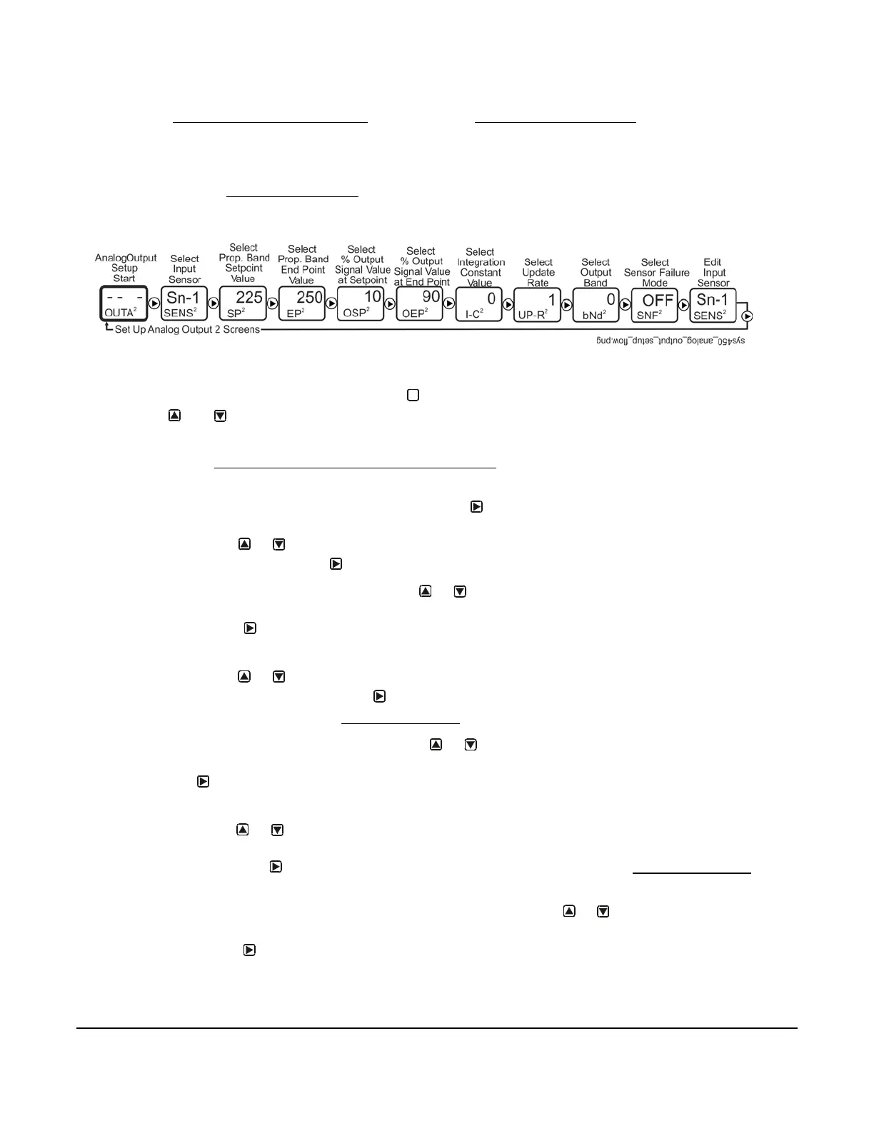
5. In the Select Output Signal Strength at Setpoint (OSP
x
) screen, press or to select the value in percent
of the output signal strength (0 to 100%), corresponding to the lowest output capacity, when the sensor is at
Setpoint (SP
x
). Press to save the displayed OSP value and go to the next screen.
Figure 29: Analog Output Setup Start Screen and Setup Screens Flow
M
 Loading...

