System 450™ Series Modular Control Systems with Standard Control Modules Technical Bulletin
41
• An output’s type (relay or analog) and output’s ID number in the UI is determined by the output types on the
control module and any connected expansion modules and the order in which the modules are connected in
the module assembly. (See Module Assemblies, Output Types, and Output Numbers
on page 7 for more
information.)
• An output’s setup parameters are determined by the output’s type (relay or analog) and the Sensor Type of the
sensor you select for the output to reference. (See Expansion Modules, Module Assemblies, and Outputs
on
page 7 and System 450 Control System Examples
on page 25 for more information.)
• In System Setup screens with flashing values, you can change the parameter value by pressing or .
When the desired parameter value is flashing in the setup screen, press to save the selected value and go
to the next setup screen.
• After 2 minutes of inactivity in a System Status or System Setup screen, the LCD reverts back to the Main
screens.
Accessing and Navigating the User Interface
System 450 control modules feature a backlit LCD and a four-button touchpad UI for monitoring system status and
setting up the sensors and outputs in your control system. Figure 1 on page 5 describes the System 450 UI
features and functions.
During normal operation, the System 450 control module LCD displays the Main screens. The Main screens are
the sensor status screens, which scroll automatically and provide real-time status of the conditions sensed at the
hard-wired and functional sensors.
Figure 21 shows an example of the System 450 Main screens and System Status screens.
Viewing the System Status Screens
From the Main screens, you can scroll through and view the System Status screens.
To view the system status screens, while the control module LCD is auto-scrolling through Main screens, press
(repeatedly) to scroll through and display the Sensor Status screens and the Output Status screens for all sensors
and outputs set up in your control system.
When you stop pressing , the Sensor or Output Status screen that is being viewed is displayed for 2 minutes
before it times out and reverts to the Main screens. The 2-minute pause allows you to monitor a sensor that is
changing quickly during system setup or normal system operation.
System 450 Main screens display the status at the hard-wired Sn-1, Sn-2, and Sn-3 sensors, and the statuses of
the functional sensor Sn-d when used in the control system. The System Status screens also display hard-wired
and functional sensor statuses along with output statuses.
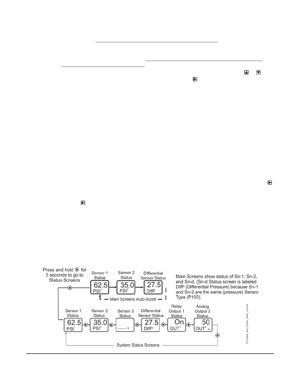
Figure 21 shows the Main screens (sensor status) and the System Status screens (sensor and output status) for a
standard System 450 control system that is set up for differential pressure control.
Figure 21: Main Screens and System Status Screens Example for a Standard System
450 Control System Set Up for Differential Control
 Loading...

