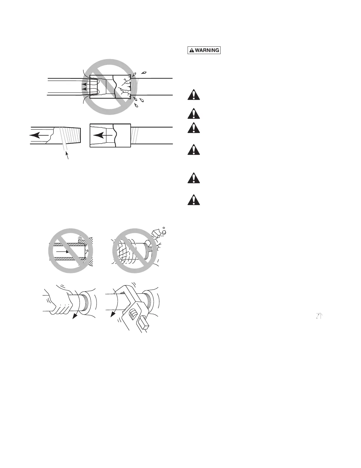
3. Wrap 1-1/2 to two layers of PTFE pipe thread
sealant tape clockwise (as you face end of pipe) on
all male threads being attached to pump.
4. Tighten joints hand tight plus 1-1/2 turns. Do not
overtighten.
NOTICE: Install pump as close to well head as poss-
ible. Long piping runs and many fittings create friction
and reduce flow.
NOTICE: For long horizontal pipe runs, install a
priming tee between check valve and well head as
shown in Figure 1. For driven point installations, install
a check valve as shown in Figure 2. Be sure check
valve flow arrow points toward pump.
Use schedule 80 or iron pipe. See “Well Pipe In stalla-
tion” for more information.
Electrical Installation
Hazardous voltage. Can shock, burn,
or cause death. Disconnect power to motor before
working on pump or motor. Ground motor before
connecting to power supply.
WIRING
Ground motor before connecting to electrical
power supply. Failure to ground motor can
cause severe or fatal electrical shock hazard.
Do not ground to a gas supply line.
To avoid dangerous or fatal electrical shock,
turn OFF power to motor before working on
electrical connections.
Supply voltage must be within ±10% of
nameplate voltage. Incorrect voltage can
cause fire or damage motor and voids warranty. If
in doubt consult a licensed electrician.
Use wire size specified in Wiring Chart, below.
If possible, connect pump to a separate
branch circuit with no other appliances on it.
Wire motor according to diagram on motor
nameplate. If nameplate diagram differs from
diagrams above, follow nameplate diagram.
1. Install, ground, wire and maintain this pump in
accordance with electrical code requirements.
Consult your local building inspector for information
about codes.
2. Provide a correctly fused disconnect switch for
protection while working on motor. Consult local or
national electrical codes for switch requirements.
3. Disconnect power before servicing motor or pump.
If the disconnect switch is out of sight of pump,
lock it open and tag it to prevent unexpected power
application.
4. Ground the pump permanently using a wire of the
same size as that specified in wiring chart, below.
Make ground connection to green grounding
terminal under motor canopy marked GRD. or
.
5. Connect ground wire to a grounded lead in the
service panel or to a metal underground water pipe
or well casing at least 10 feet long. Do not connect
to plastic pipe or insulated fittings.
6. Protect current carrying and grounding conductors
from cuts, grease, heat, oil, and chemicals.
7. Connect current carrying conductors to terminals L
1
and L
2
under motor canopy. When replacing motor,
check wiring diagram on motor nameplate against
Figure 8, Page 6. If the motor wiring diagram does
not match either diagram in Figure 8, follow the
diagram on the motor.
5
Figure 7 – Don’t overtighten
Don’t Hit
Thread Stops
Overtighten
From
Well
Pump
Body
Hand Tight Plus 1-1/2 Turns With Wrench.
Figure 6 – Use PTFE pipe thread sealant tape or
Plasto-Joint Stik on pipe joints and connections to
pump
No Air Leaks
in Suction Pipe.
Compound Will
Damage Plastic.
If Air Flows
Water Won’t
Use PTFE Tape