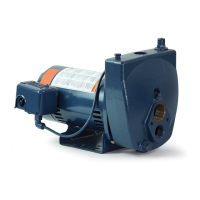
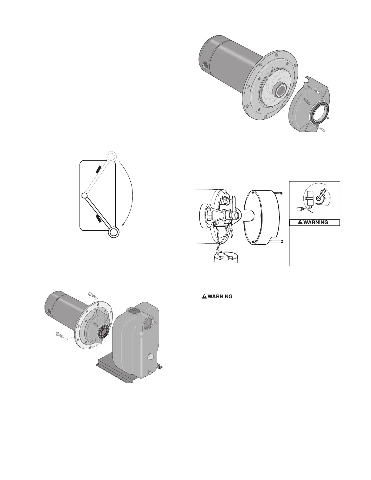
Maintenance
Pump and piping need not be disconnected to repair
or replace motor or seal (see Figure 14). If motor is
replaced, replace the shaft seal (Key No. 7, Page 12).
Keep one on hand for future use.
Be sure to prime pump before starting.
NOTICE: Check motor label for lubrication instructions.
The mechanical shaft seal in the pump is water
lubricated and self-adjusting.
NOTICE: Drain pump when disconnecting from service
or when it might freeze.
PUMP DISASSEMBLY
1. Disconnect power to motor.
NOTICE: Mark wires for correct assembly.
2. Remove capscrews holding seal plate to pump
body. Motor assembly and seal plate can now be
pulled away from pump body (Figure 14). CARE-
FULLY remove gasket.
CLEANING/REPLACING IMPELLER
NOTICE: First, follow instructions under “Pump Dis-
assembly”.
1. Remove screws fastening diffuser to seal plate;
re move diffuser (see Figure 15). Exposed impeller
can now be cleaned.
2. If impeller must be replaced, loosen two machine
screws and remove motor canopy (see Figure 16).
3.
Capacitor voltage may be
hazardous. To discharge capacitor, hold insulated
handle screwdriver BY THE HANDLE and short
capacitor terminals together (see Figure 16). Do not
touch metal screwdriver blade or capacitor terminals.
If in doubt, consult a qualified electrician.
4. Unscrew capacitor clamp and remove capacitor. Do
not disconnect capacitor wires to motor.
5. Slide 7/16” open end wrench in behind spring
loaded switch on motor end of shaft; hold motor
shaft with wrench on shaft flats and unscrew
impeller screw (if used) by turning clockwise (left
hand thread) when looking into eye of impeller.
6. Unscrew impeller while holding shaft by turning
counterclockwise while looking into eye of impeller.
7. To reinstall, reverse steps 1 through 6.
8. See directions under “Pump Reassembly,” Page 10.
8
ON
OFF
Figure 13 – Disconnect Power
Figure 14 – Slide Motor Back
Figure 15 – Remove Diffuser
Figure 16 – Hold Shaft
To avoid electrical
shock hazard, use
insulated-handle
screwdriver to short
capacitor terminals
as shown.