EasyManua.ls Logo

Pentair Goyen IS Series User Manual

Pentair Goyen IS Series
8 pages
To Next Page IconTo Next Page
Page #1 background imageLoading...
Page #1 background image
1/56
©COPYRIGHT Goyen Controls Co. Pty. Ltd.
DESCRIPTION
The Integrato Sequencer (IS & ISP) features integrated controls
intended for use with larger reverse pulse jet filter cleaning
systems. The IS & ISP have been designed to operate across a
wide range of environmental conditions. It is suitable for use with
all types of filters, including bags, cartridges, sintered metal or
ceramic filters.
The IS sequencer operates in continuous mode, whereas the ISP
has a built-in differential pressure sensor, allowing this sequencer
to be demand driven.
IS & ISP may be ordered as the sequencer only or in an enclosure
(polycarbonate).
TECHNICAL CHARACTERISTICS & PERFORMANCE
dP Support 0 to 4.5 kPa
Input Voltage AC: 85–275 V @ 50/60 Hz
Output Voltage AC: 85–275 V @ 50/60 Hz (same as input)
DC: 24 V
Maximum Input Power AC IN, AC OUT Model: 225 W
AC IN, DC OUT Model: 65 W
Discrete Solenoid Outputs 12, 20 or 40 outputs
Enclosure Polycarbonate or no enclosure
Protection Rating Polycarbonate: NEMA 1, 3, 3S, 4, 4X, 6,
6P & 12, IP65
Operating Temperature
Non-ATEX approved products:
40°C to +70°C (40°F to +158°F)
Non-ATEX approved products with 3 DC
pilot valves in parallel:
20°C to +70°C (4°F to +158°F)
ATEX approved enclosure products:
20°C to +50°C (4°F to +122°F)
ON & OFF Time ON: 30 ms to 1000 ms, OFF: 1 s to 1000 s
Inputs Voltage Free: Fan Stop, Low Header Alarm
Outputs Voltage Free: Coil Error.
Analogue Output: 4–20 mA dP signal on
the ISP
Controls up to 40 individual outputs.
AC outputs can have up to 10 pilot valves
connected in parallel.
DC outputs can have up to 3 pilot valves
connected in parallel.
See Operating Temperature for more
details.
IS/ISP units inside a polycarbonate enclosure have ATEX approval:
II 3 D Ex tc IIIC T52°C Dc Tamb: -20°C to +50°C
WARNING: POTENTIAL ELECTROSTATIC CHARGING HAZARD.
CLEAN ONLY WITH A DAMP CLOTH.
WARNING: FOR BARE BOARD PRODUCTS, USE AN
APPROPRIATE ENCLOSURE.
WARNING: FOR ATEX APPLICATION DO NOT OPEN WHEN
ENERGISED OR WHEN AN EXPLOSIVE ATMOSPHERE IS PRESENT.
PRODUCT INSTALLATION INSTRUCTIONS
GOYEN IS/ISP SERIES CONTROLLER
DEINE-012
ISSUE: 9 DATE: 11.08.2017
CIRCUIT BOARD LAYOUT
ISP12
ISP40
1 AC Input Voltage: Electrical connection to the board. Active, Earth
and Neutral connections. Cable size 14–20 AWG for the phase
conductors, with the earth wire being greater or equal to the
phase conductors.
2 ON:OFF Power Switch: Switch power the board ON and OFF.
3 Fuse (Over Current Protection): Replacement fuse T2.5 A 250 V
(slow blow).
4 Outputs Common Terminal: This is the common terminal for all
the 12 solenoid outputs. Cable size 12–20 AWG.
5 Discrete Solenoid Output Terminals: Connect each solenoid wire
to a separate output terminal. Cable size 12–20 AWG.
6 Coil Alarm Output (Voltage Free): This output triggers when the
coil fails to pulse correctly. It may indicate a fault with the coil or
wiring to that coil. Normally Open. A closed contact will indicate
a coil error. Cable size 14–26 AWG.
7 4–20 mA dP Output: This output mirrors the output of the built in
dP sensor in the form of a 4–20 mA signal. (ISP only)
8 Low Header Alarm Input (Voltage Free): This input allows for
the connection of a sensor to monitor the header tank pressure.
In the event the pressure drops below the preset level, the
pulsing cycle is paused. Normally Open. A closed contact will
pause the cleaning cycle. displaying LoH. Cable size 14–26 AWG.
9 Fan Stop Input (Voltage Free): This input is used to stop the
controller remotely. It may be connected to the blower fan control
so the cleaning cycle automatically pauses in the event the fan
stops. Normally Open. A closed contact will stop the cleaning
cycle, displaying FSP. Cable size 14–26 AWG.
IS/ISP SERIES
INTEGRATO SEQUENCER
ENGLISH
1
2
3
4
5
7
6
8
9
10
11
12
13
14
15
5
4
16
3
1
2
4
5
6
7
8
9
10
11
12
13
14
15
16
Question and Answer IconNeed help?

Do you have a question about the Pentair Goyen IS Series and is the answer not in the manual?

Pentair Goyen IS Series Specifications

General IconGeneral
EnclosureIP65
TypeController
Voltage24V DC
Protection ClassNEMA 4
SeriesIS Series

Summary

DESCRIPTION

Integrato Sequencer Overview

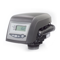
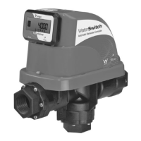
Overview of Goyen IS/ISP Integrato Sequencer for filter cleaning systems.

TECHNICAL CHARACTERISTICS & PERFORMANCE

Technical Specifications Summary

Details on dP support, voltage, power, outputs, enclosure, temperature, and timing.

CIRCUIT BOARD LAYOUT

ISP12 and ISP40 Circuit Diagrams

Visual diagrams showing the layout of ISP12 and ISP40 circuit boards.

Circuit Board Terminal Functions

Explanations for numbered terminals 1-9 on the IS/ISP circuit boards.

INTERFACE MODULE FUNCTIONS

IS Interface Module

Description of the functions and display for the IS interface module.

ISP Interface Module

Description of the functions and display for the ISP interface module.

PROGRAMMING INSTRUCTIONS

Entering Programming Mode

Steps to access and navigate the controller's programming mode.

Setting dP Low Limit

Procedure to configure the low differential pressure limit for demand mode.

Setting dP High Limit

Procedure to configure the high differential pressure limit for demand mode.

Setting dP Units

Configuration of units for differential pressure measurement (kPa or InWG).

Setting High dP Alarm

Procedure to set the threshold for the high differential pressure alarm.

Setting On Time

Configuration of the solenoid pulse duration in milliseconds.

Setting Off Time

Configuration of the solenoid rest time between pulses in seconds.

Setting Blowdown Cycles

Configuration of the number of blowdown cycles for the system.

Exiting Programming Mode

Procedure to exit programming mode and save settings.

OPERATION OF THE CONTROLLER

Controller Startup Behavior

Description of controller actions and displays upon power-up.

Display Modes

Explanation of displays in continuous and demand operating modes.

OUTPUTS AND ALARMS

Alarm Indicators

Explanation of 'FSP' (Fan Stop) and 'LoH' (Low Header) alarm displays.

Output Fault Displays

Indication of short circuit ('-IXX') or open circuit ('oXX') on pilot valves.

REPLACEMENT FUSE INFORMATION

Fuse Specifications Table

List of recommended fuse types and part numbers for replacement.

INSTALLATION INSTRUCTIONS

General Installation Warnings

Important safety precautions and warnings for installation.

ATEX Application Warnings

Specific warnings for ATEX environments and equipment.

INSTALLATION STEPS

Step 1: Enclosure Mounting

Instructions and diagrams for securely mounting the enclosure.

Step 2: Connect Inputs and Outputs

Guidance on connecting input and output wiring to the controller.

Step 3: Connect dP Air Lines

Instructions for connecting differential pressure air lines (ISP only).

Step 4: Connect Solenoid Outputs

Instructions for connecting discrete solenoid output wiring.

Step 5: Connect Input Voltage

Guidance for making the main AC input voltage connections.

Step 6: Connect Interface Module

Procedure for connecting the external interface module.

Step 7: Inspect Connections

Check all wiring and connections before applying power.

Step 8: Power Up and Settings Check

Initial power-on procedure and verification of settings.

Step 9: Test Performance

Procedure to test the controller's operational performance.

WIRING DIAGRAM

Controller Wiring Diagram

Schematic illustrating the electrical connections for the controller.

MAINTENANCE

Cleaning Procedure

Instructions for cleaning the controller and enclosure.

Fuse Replacement

Procedure for safely replacing a blown fuse.

EU DECLARATION OF CONFORMITY

Product Conformity Statements

Declarations of conformity for various directives including ATEX and LVD.

ATEX Approval Details

Specific ATEX certification information for the pilot valve enclosure.

Harmonised Standards Applied

List of relevant harmonised standards used for product certification.

Related product manuals