Rev. B 8/14 MASTERTEMP
®
125 Pool and Spa Heater Installation and User’s Guide
13
BELOW POOL INSTALLATION
,IWKHKHDWHULVEHORZZDWHUOHYHOWKHSUHVVXUHVZLWFKPXVWEHDG
MXVWHG7KLVDGMXVWPHQWPXVWEHGRQHE\DTXDOL¿HGVHUYLFHWHFKQL
FLDQ6HHIROORZLQJ&$87,21EHIRUHLQVWDOODWLRQ
CAUTION
BELOW OR ABOVE POOL INSTALLATION
The water pressure switch is set in the factory at 3.00 PSI (± 0.75 PSI). This setting is for a heater installed at pool level.
If the heater is to be installed more than 1’ above or below, the water pressure switch must be adjusted by a qualified
service technician. See page 34, Figure 29.
FLOW SWITCH
If the heater is installed more than 5’ above the pool or more than 4’ below the pool level, you will be beyond the limits
of the pressure switch and a flow switch must be installed. Locate and install the flow switch externally on the outlet
piping from the heater, as close as possible to the heater. Connect the flow switch wires in place of the water pressure
switch wires.
Section 3. Installation Instructions
VALVES
:KHQDQ\HTXLSPHQWLVORFDWHGEHORZWKHVXUIDFHRIWKHSRRORUVSDYDOYHVVKRXOGEHSODFHGLQWKHFLUFXODWLRQSLSLQJ
V\VWHPWRLVRODWHWKHHTXLSPHQWIURPWKHSRRORUVSD&KHFNYDOYHVDUHUHFRPPHQGHGWRSUHYHQWEDFNVLSKRQLQJ%DFN
VLSKRQLQJLVPRVWOLNHO\WRRFFXUZKHQWKHSXPSVWRSVFUHDWLQJDSUHVVXUHVXFWLRQGLIIHUHQWLDO'R127VDQLWL]HWKH
SRROE\SXWWLQJFKORULQHWDEOHWVRUVWLFNVLQWRWKHVNLPPHUV:KHQWKHSXPSLVRIIWKLVZLOOFDXVHDKLJKFRQFHQWUDWLRQ
RIFKORULQHWRHQWHUWKHKHDWHUZKLFKFRXOGFDXVHFRUURVLRQGDPDJHWRWKHKHDWH[FKDQJHU
CAUTION
Exercise care when installing chemical feeders so as to not allow back siphoning of chemical into the heater, filters or
pump. When chemical feeders are installed in the circulation of the piping system, make sure the feeder outlet line is
down stream of the heater, and is equipped with a positive seal noncorrosive “Check Valve”, (P/N R172288), between
the feeder and heater.
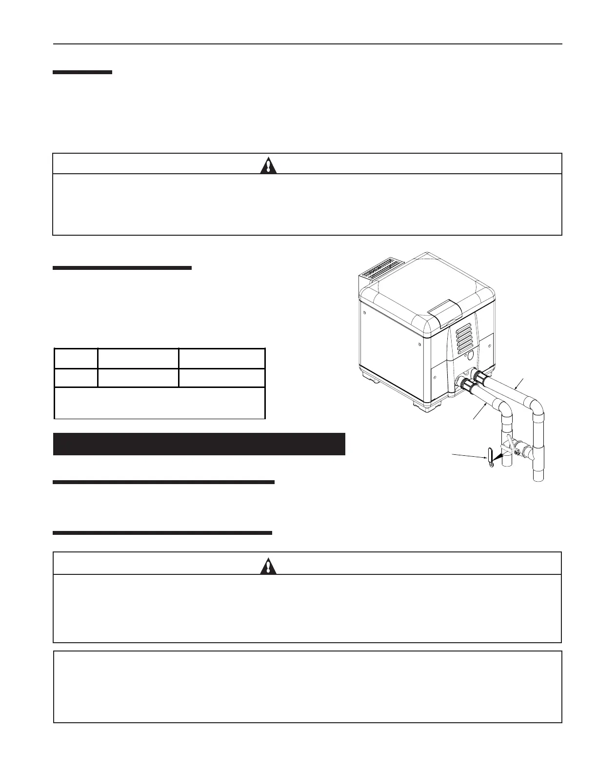
MANUAL BY-PASS
:KHUHWKHZDWHUÀRZUDWHH[FHHGVWKHPD[LPXP*30/30
DPDQXDOE\SDVVVKRXOGEHLQVWDOOHGDQGDGMXVWHG$IWHULQVWDOOLQJWKH
YDOYHDGMXVWWKHYDOYHWREULQJWKHÀRZUDWHZLWKLQWKHDFFHSWDEOH
UDQJH7KHQ UHPRYH WKH YDOYH KDQGOH RU ORFN LW LQ SODFH WR DYRLG
WDPSHULQJ6HH
)LJXUH
Table 1.
See page 34 for Pressure Relief Valve Installations.
Cool water in
Warm water out
OUTLET TO POOL
INLET FROM HEATER
1. Set Manual By-Pass Valve.
2. Remove Handle.
Model Min. (GPM) (LPM) Max. (GPM) (LPM) *
125 20 (76) 70 (265)
* Do not exceed the maximum recommended flow
rate for the connecting piping.
Figure 5.

 Loading...