27
and rollers) on the shaft is to heat the cone assembly
in an electric oven for 30 minutes at 300 to 400ºF. No
more! (DO NOT heat bearings with an acetylene torch.
This ruins the bearings!) Using clean, insulated gloves,
remove the hot cone assembly from the oven, promptly
dropping it on to the shaft.
The cone assembly MUST contact the seat thrust face
(not be cocked), and the large end of the rollers MUST
be down. Do not hammer on the bearing. The soft steel
cage is easily distorted, ruining its function as a roller
separator and guide against skewing. If the cone does
not contact its thrust face properly, it must be pressed
into place using a specially machined sleeve (which
does not touch the soft steel cage). A hydraulic press is
recommended if this difficulty arises.
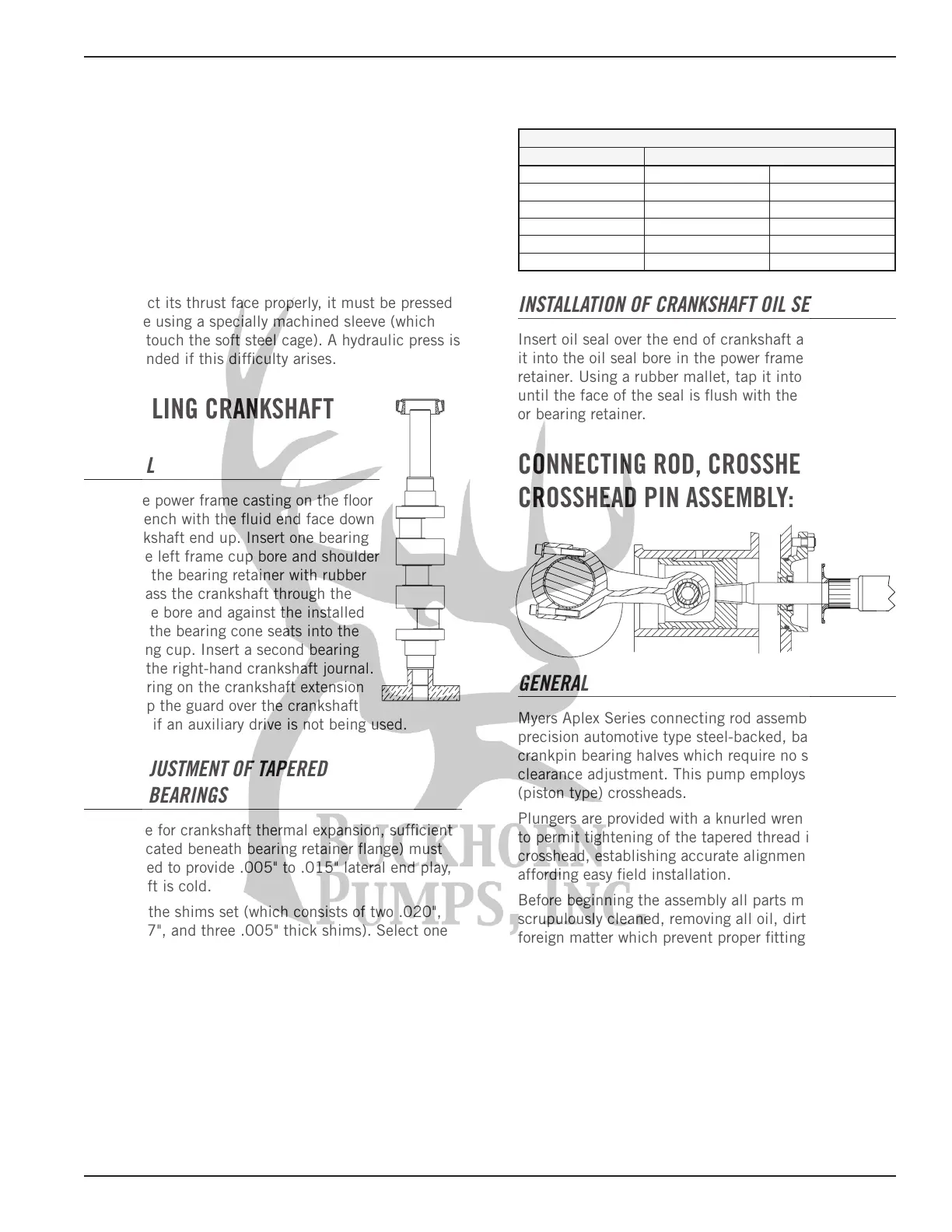
INSTALLING CRANKSHAFT
GENERAL
Stand the power frame casting on the floor
or on a bench with the fluid end face down
and crankshaft end up. Insert one bearing
cup in the left frame cup bore and shoulder
it against the bearing retainer with rubber
mallet. Pass the crankshaft through the
right frame bore and against the installed
cup until the bearing cone seats into the
left bearing cup. Insert a second bearing
cup over the right-hand crankshaft journal.
Install O-ring on the crankshaft extension
guard. Tap the guard over the crankshaft
extension if an auxiliary drive is not being used.
SHIM ADJUSTMENT OF TAPERED
ROLLER BEARINGS
To provide for crankshaft thermal expansion, sufficient
shims (located beneath bearing retainer flange) must
be installed to provide .005" to .015" lateral end play,
when shaft is cold.
Separate the shims set (which consists of two .020",
three .007", and three .005" thick shims). Select one
.020" shim and the bearing retainer and position them
over the bearing retainer.
Insert two of six hex head cap screws 180º apart and
tighten alternately until the bearing cup is seated.
Place a magnetic base indicator on the exposed end of
the crankshaft with indicator spindle against the side
of power frame. Move crankshaft laterally with a pry bar
first left and then right observing movement indicated
in each direction. The lateral end play should be only
.005" to .015". Remove the bearing retainer and add
shims as needed. Repeat the procedure above until
the proper end play tolerance is obtained. Install the
remaining four cap screws.
Tightening Torque for Tapered Bearings
3/8-16-24-30 Ft.-Lb. 1/2-13 59-72 Ft.-Lb.
MA-15M MA-25L SC-45H
MA-15H MA-25M SC-65
SC-30 MA-40L SC-65L
SC-30H MA-40M SC-65H
RO-23 SC-45 RO-38
SC-45L RO-64
INSTALLATION OF CRANKSHAFT OIL SEAL
Insert oil seal over the end of crankshaft and position
it into the oil seal bore in the power frame or bearing
retainer. Using a rubber mallet, tap it into the bore
until the face of the seal is flush with the power frame
or bearing retainer.
CONNECTING ROD, CROSSHEAD AND
CROSSHEAD PIN ASSEMBLY:
GENERAL
Myers Aplex Series connecting rod assemblies employ
precision automotive type steel-backed, babbitt-lined
crankpin bearing halves which require no shims for
clearance adjustment. This pump employs full-circle
(piston type) crossheads.
Plungers are provided with a knurled wrenching area
to permit tightening of the tapered thread into the
crosshead, establishing accurate alignment while
affording easy field installation.
Before beginning the assembly all parts must be
scrupulously cleaned, removing all oil, dirt, rust, and
foreign matter which prevent proper fitting, or which
might tend to score the rubbing surfaces. Clean
and examine the power frame bores for scoring and
abnormal wear, especially wear of the lower crosshead
guide way. Hone smooth, if rough.
Measure the bores of the frame using inside
micrometers to determine abnormal frame wear if any.
 Loading...