28 29
Crosshead O.D.:
2.622/2.619
New Frame Bores:
2.625/2.628
Crosshead O.D.:
3.243/3.246
New Frame Bores:
3.253/3.250
Crosshead O.D.:
3.996/3.993
New Frame Bores:
4.000/4.004
MA-15M MA-25M MA-40L
MA-15H MA-25L MA-40M
SC-30 SC-45 SC-65
SC-30H SC-45L SC-65H
RO-23 SC-45H SC-65L
RO-38 RO-64
Frame bores which have become worn more than
0.015" must be sleeved with a cast iron liner to
reestablish correct geometry and alignment. Contact
Aurora pump, Aplex series concerning badly worn
frame bores.
Smooth any rough corners and edges on the crosshead
skirts, using fine emery cloth. Examine and clean the
female tapered threads and wrist pin holes.
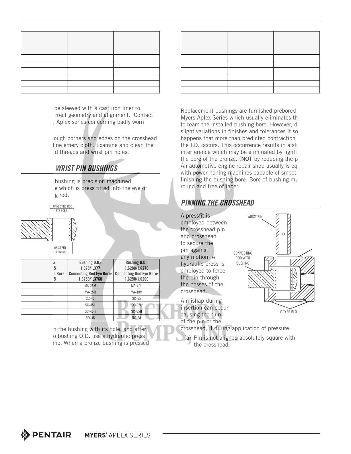
INSTALLING WRIST PIN BUSHINGS
The wrist pin bushing is precision machined
bearing bronze which is press fitted into the eye of
the connecting rod.
Bushing O.D.:
1.0625/1.0645
Connecting Rod Eye Bore:
1.0625/1.0635
Bushing O.D.:
1.378/1.377
Connecting Rod Eye Bore:
1.3750/1.3760
Bushing O.D.:
1.6280/1.6270
Connecting Rod Eye Bore:
1.6250/1.6260
MA-15M MA-25M MA-40L
MA-15H MA-25H MA-40M
SC-30 SC-45 SC-65
SC-30H SC-45L SC-65L
RO-23 SC-45H SC-65H
RO-38 RO-64
Carefully align the bushing with its hole, and after
applying oil to bushing O.D. use a hydraulic press
to force it home. When a bronze bushing is pressed
into place, the I.D. (bore) of the bushing is reduced
somewhat, owing to the extent of press fit. Therefore,
a clean, new wrist pin should be inserted into the
bushing bore to establish that running clearance has
been obtained. The running clearance between the
wrist pin and installed bushing is:
New Pin O.D.:
0.8140/0.8135
Installed Bushing Bore:
0.8145/0.8150
New Pin O.D.:
1.0640/1.0635
Installed Bushing Bore:
1.0645/1.0650
New Pin O.D.:
1.3140/1.3135
Installed Bushing Bore:
1.3145/1.3155
MA-15M MA-25L MA-40L
MA-15H MA-25M MA-40M
SC-30 SC-45 SC-65
SC-30H SC-45L SC-65L
RO-23 SC-45H SC-65H
RO-38 RO-64
Oil Clearance ........................................0005/.0015"
Replacement bushings are furnished prebored by
Myers Aplex Series which usually eliminates the need
to ream the installed bushing bore. However, due to
slight variations in finishes and tolerances it sometimes
happens that more than predicted contraction of
the I.D. occurs. This occurrence results in a slight
interference which may be eliminated by lightly honing
the bore of the bronze. (NOT by reducing the pin size!)
An automotive engine repair shop usually is equipped
with power honing machines capable of smoothly
finishing the bushing bore. Bore of bushing must be
round and free of taper.
PINNING THE CROSSHEAD
A pressfit is
employed between
the crosshead pin
and crosshead
to secure the
pin against
any motion. A
hydraulic press is
employed to force
the pin through
the bosses of the
crosshead.
A mishap during
in sertion can occur
caus ing the ruin
of the pin or the
crosshead, if during application of pres sure:
(a) Pin is not aligned absolutely square with
the crosshead.
(b) Crosshead is not sup ported on v-blocks so it can
roll while under load.
(c) Con necting rod is not ful ly support ed so pin
cannot en ter the bushing without damage to it.
This will damage the bush ing.
(d) Fail ure to oil pin O.D. and crosshead bores, to
prevent galling. Use clean motor oil.
After in stalling the pin, carefully check the crosshead
O.D. to see if it is out-of-round. If so, a smart blow with
WRIST PIN
CONNECTING
ROD WITH
BUSHING
CONNECTING ROD
EYE BORE
WRIST PIN
 Loading...