EQUIPMENT INSTALLATION continued
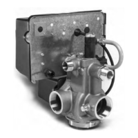
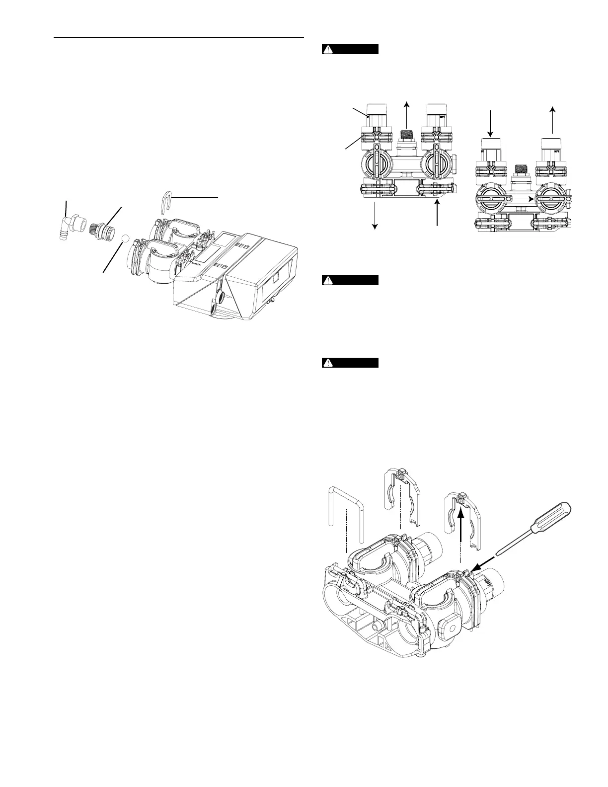
Drain Line Flow Control
The drain line ow control (DLFC) requires assembly
(Figure 5).
1. Locate parts and a roll of plumber's tape.The plumbing
adapters should be removed (Figure 7 Connector
Assembly).
2. Wrap the tape over threads of the ow control.
3. Screw the ow control and the 90° elbow together. Hand
tighten.
4. Place the ball into the ow control and insert the assembly
into the drain line opening.
5. Push the assembly in and secure with the drain line clip.
90° Elbow
Flow Control
Control Ball
Drain Line Clip
Figure 5
Water Line Connection
A bypass valve system is included and will be installed on the
water conditioning system. Bypass valves isolate the softener
from the water system and allow unconditioned water to be
used. Service or routine maintenance procedures may also
require that the system is bypassed.
IMPORTANT: The bypass valve is shipped to you in the
bypass position (Figure 6 Bypass Operation). When the
valve is in bypass water will not enter the softening tank.
The water in the building will not be treated. Figure 6
Bypass Operation, shows the handles in the service
position.
Once you have selected your location check the direction of
the waterow in the main pipe. Figure 6 Bypass Operation can
be used to plan the new plumbing assembly.
Inspect the main water pipe. Write down the type of pipe
(copper, plastic, galvanized etc.). Record the size of the pipe.
Plastic style pipes usually have the size printed on the outside.
Other pipes can be measured for the outside diameter and
converted into the pipe size at the store. Do not use pipe that is
smaller than the main water pipe.
The bypass has two ttings that connect to the plumbing.
These connections are threaded 1" NPT.
If the main plumbing is galvanized pipe and you are installing
copper pipe, then you must use dielectric insulating connectors
between the two styles of pipe.
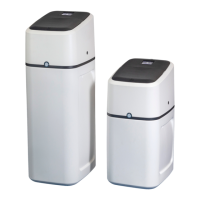
Place the two tanks in position. The design of the tank does not
allow for bad alignment of the connections. You may ask your
supply store about exable connections.
Take measurements and create a drawing of your installation.
Include pipe lengths and elbows that are needed. If the water
ow is from right to left you will need to cross the plumbing to
the softener. Take the drawing to your plumbing supply store.
Consult with their expert for installation ideas and suggestions.
Assemble the plumbing.
If pipes will be sweat soldered, do not
connect adapters to the bypass until the
pipes have cooled.
IN OUT
IN OUT
Connector
Assembly
“H” Clip
Drain
Line
Handles in Service Handles in Bypass
Figure 6 Bypass Operation
The inlet water must be connected to the
inlet port of the valve. When replacing
non-Omni Water valves, it is possible that
the inlet and outlet plumbing is installed
in a reversed position. Be certain the inlet
connection on the valve is connected to the
incoming water tting from the water supply.
Do not solder pipes with lead-based solder.
Do not use petroleum grease on gaskets
when connecting bypass plumbing. Use
only 100% silicone grease products when
installing any plastic valve. Non-silicone
grease may cause plastic components to fail
over time.
The bypass assembly connects to the water system by means
of a connector assembly. The connector is secured to the
plumbing and then inserted into the bypass. A clip is used to
hold it in place.
Figure 7 Connector Assembly
Before inserting the connector:
• Check that all O-rings are in place and not damaged.
• O-rings are pre-lubricated. Sliding surfaces should be
lubricated with 100% silicone grease.
Firmly insert connector into bypass. Press locking clip into
position. Make certain the clip is fully engaged.
OM26K • 7
 Loading...