NOTE: Before turning on the water to the valve, rotate the
two handles on the bypass valve 2-3 times. This
will help seat O-rings and prevent leaking.
To remove a clip:
1. Turn off water and release water pressure at the valve.
2. Push the water line connectors into the bypass and valve.
This will help release O-rings that may have seated in
place.
3. Remove the clip by inserting a at blade under the top
center of the clip and lifting (prying up) (Figure 7 Connector
Assembly).
Do not use pliers to remove a clip. It is likely
the clip will break.
Drain Line Connection
NOTE: Standard commercial practices are expressed here.
Local codes may require changes to the following
suggestions. Check with local authorities before
installing a system.
1. The unit should be above and not more than 20 feet (6.1 m)
from the drain. Use an appropriate adapter tting to connect
1/2-inch (1.3 cm) plastic tubing to the drain line connection
of the control valve.
2. If the unit is located 20-40 feet (6.1-12.2 m) from drain, use
3/4-inch (1.9 cm) tubing. Use appropriate ttings to connect
the 3/4-inch tubing to the 3/4-inch NPT drain connection on
valve.
3. The drain line may be elevated up to 6 feet (1.8 m)
providing the run does not exceed 15 feet (4.6 m) and
water pressure at the softener is not less than 40 psi (2.76
bar). Elevation can increase by 2 feet (61 cm) for each
additional 10 psi (.69 bar) of water pressure at the drain
connector.
4. Where the drain line is elevated but empties into a drain
below the level of the control valve, form a 7-inch (18-cm)
loop at the far end of the line so that the bottom of the loop
is level with the drain line connection. This will provide an
adequate siphon trap.
Where the drain empties into an overhead sewer line, a
sink-type trap must be used.
NOTE: The drain line connects to the elbow previously
installed. It is located between the water line
connections at the rear of the valve.
5. Use pliers to expand a clamp. Slide the clamp up one end
of the longer length drain line tubing about 1-2 inches and
release.
6. Push the tubing over the ribbed drain line tting.
7. Expand the clamp and move it up the tube to pinch the tube
to the ftitting.
8. Secure the discharge end of the drain line to prevent it from
moving.
Right Way
Figure 8 Drain Line Connection
NOTE:
Waste connections or drain outlet shall be
designed and constructed to provide for
connection to the sanitary waste system through
an air-gap of 2 pipe diameters or
1 inch (22 mm) whichever is larger.
Never insert drain line directly into a
drain, sewer line, or trap (Figure 8 Drain
Line Connection). Always allow an air gap
between the drain line and the wastewater
to prevent the possibility of sewage being
back-siphoned into the softener.
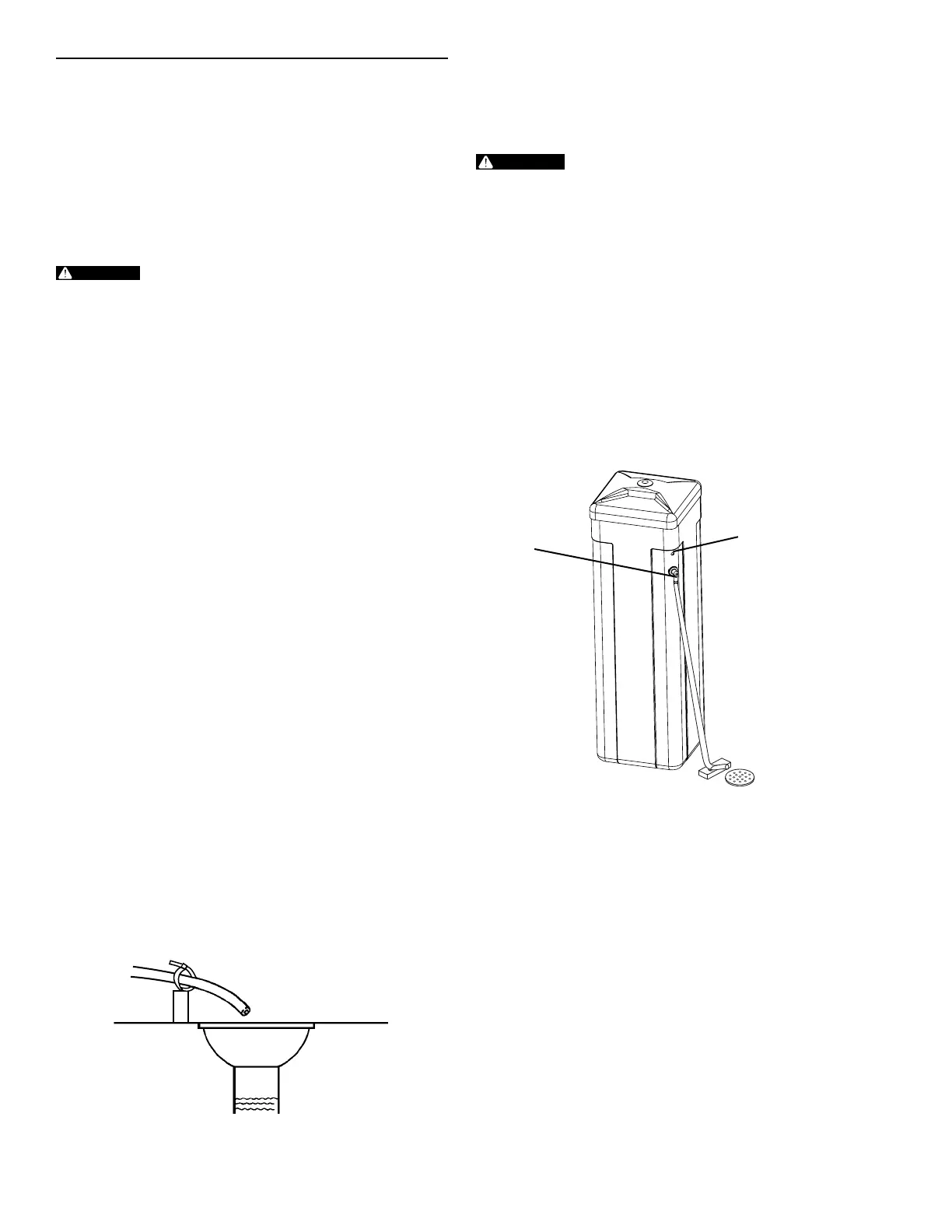
Overow Line Connection
In the event of a malfunction, the salt TANK OVERFLOW will
direct “overow” to the drain instead of spilling on the oor. This
tting should be on the side of the cabinet.
To connect the overow line, locate the tubing connector on the
side of the tank (Figure 9 Tubing Connections). Attach length of
1/2-inch (1.3-cm) I.D. tubing to tting and run to drain. Do not
elevate overow line higher than overow tting.
Do not tie into drain line of control unit. Overow line must be a
direct, separate line from overow tting to drain, sewer or tub.
Allow an air gap as per drain line instructions.
Overow
Connection
Salt Line Opening
Figure 9 Tubing Connections
EQUIPMENT INSTALLATION continued
8 • OM26K
 Loading...