INSTALLATION
NOTE: For cold water use only.
NOTE: Make certain that installation complies with all state
and local laws and regulations.
NOTE: The contaminants or other substances removed or
reduced by the selected cartridge are not necessarily
in your water. Filter must be maintained according
to manufacturer’s recommendation including
replacement of filter cartridges. Ask your local water
municipality for a copy of their water analysis, or
have your private well tested by a reputable water
testing lab.
NOTE: After prolonged periods of non-use (such as during
a vacation) it is recommended that the system be
flushed thoroughly. Let water run for 2-3 minutes
before using.
NOTE: The filter cartridge used with this system has a
limited service life. Changes in taste, odor, color,
and/or flow of the water being filtered indicate that
the cartridge should be replaced.
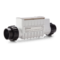
1. Mounting the Filter System
A. Select a location where filter system is to be mounted.
NOTE: Allow 1-1⁄2 inches (38 mm) clearance below housing
or 11-inches (279 mm) below filter head to enable
filter cartridge changes.
Filter head should be mounted securely to a solid
stud or surface. The mounting bracket will support
the weight of the filter and help prevent strain on
the cold water line.
B. Filter head should be mounted in vertical position. Use
mounting bracket as a template to mark screw locations.
Mount filter head in marked location using the screws
provided in the hardware kit.
Cold water supply to the filter should have a
separate shut-off valve. If it does not, a separate
shut-off should be installed.
2. Connecting the Tubing and Fittings
A. Assemble fittings as shown in Figure 2A. Press appropriate
tubing into the inlet and outlet fittings until it stops. Hand-
tighten connections. Then tighten 1 to 1-1⁄2 turn(s) with a
wrench.
B. Cut and deburr 1/4-inch or 3/8-inch tubing. Insert tubing
into push fittings. Push tubing in until you hit a hard stop as
shown in Figure 2B, page 3. To remove tubing from fitting,
depress tube collar around the tube while pulling the tube
out.
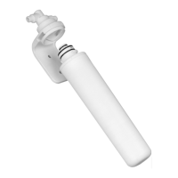
3. Installing the Cartridge
See Filter Cartridge Replacement, Step R3, for installation
instructions.
11"
11"
Inlet
Outlet
1A
Inlet
Outlet
COPPER TUBING Hand tighten plus 1 to 1-1/2 turns with a wrench
PLASTIC TUBING Hand tighten plus 1 to 1-1/2 turns with a wrench
FLEX TUBING Wrench tighten, do not over tighten
2A
1/4-inch THREADED COMPRESSION FITTINGS
1/4-inch Compression
Flexible Braided Hose
Ferrule
Nut
Ferrule
Nut
1/4" or 3/8"
Copper or Plastic
Tubing
Tube
Collar
Push tubing into fitting until you hit a hard stop.
2B
JG PUSH FIT FITTINGS
PENTEK
®
QC10 SERIES Installation and Operation Manual • 3
 Loading...