WHISPERFLOXF
®
VS and MAX-E-PROXF
®
VS Commercial Variable Speed Pump Installation and User’s Guide
19
Replacing the Drive Assembly
TO REMOVE THE EXISTING DRIVE ASSEMBLY:
1. If possible, record your programmed schedule and priming speed before proceeding.
2. Disconnect power to the pump at the circuit breaker. Wait ve minutes after disconnecting the power before
removing the drive cover.
3. Using a #2 Phillips-head screwdriver, uninstall the eld wiring compartment cover from the side of the drive. Place
the cover and all screws aside.
4. Uninstall eld wiring, strain relief and/or conduit
from the drive.
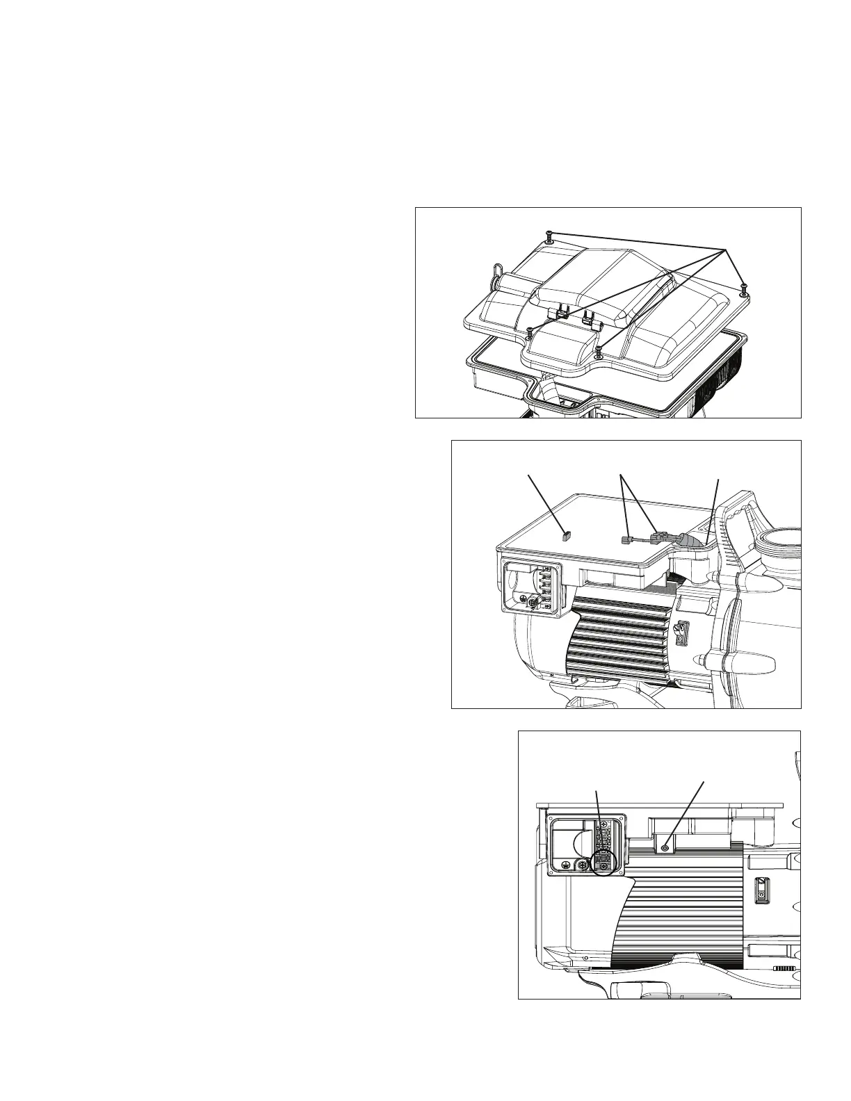
5. Using a T20 star-head screwdriver, remove the
four (4) Drive Cover Screws (Figure 22).
6. Gently lift the drive cover and disconnect the
keypad cable from the Keypad Terminal (Figure
23). Place the drive cover aside.
7. Carefully disconnect the four (4) white Motor
Connectors (Figure 23) from their ag
terminals.
Note: Take note of which terminal each
connector is paired with. Each connector must
be reconnected to the same terminal.
8. Using a T20 star-head screwdriver, remove the two
Front Drive-to-Motor Screws (Figure 23).
9. Using a T20 star-head screwdriver, remove the
two Rear Drive-to-Motor Screws (Figure 24) from
underneath the drive.
10. Lift the drive away from the motor, carefully guiding
the motor cables through the opening in the front of
the drive. Place the old drive aside.
TO REMOVE THE NEW DRIVE ASSEMBLY:
11. Place the new drive onto the motor, carefully feeding
the Motor Connections through the opening in the
front of the drive.
12. Reinstall the four Drive-to-Motor Screws (Figure 23
and Figure 24).
13. Referring back to the notes taken in Step 7, plug each
motor cable into its corresponding ag terminal.
14. Reconnect the drive cover’s keypad connector to the drive and
seat the drive cover onto the drive body.
15. Reinstall the four Drive Cover Screws (Figure 22).
16. The eld wiring compartment contains a partially installed surge
jumper. Finish installing the surge jumper between the bottom
two Screw Terminals (Figure 24).
17. Reconnect the Main Power supply and strain relief or conduit for
the electrical wires.
18. Reinstall the eld wiring compartment cover using the four cover
screws.
19. Return power to the pump at the circuit breaker.
20. Your pump’s time, schedule and priming speed will need
to be reprogrammed. Refer to the OPERATION section for
programming procedures.
Front Drive-to-Motor
Screws (x2) (Not Shown)
Figure 23
Motor
Connections
Keypad
Terminal
Drive Cover
Screws (x4)
Figure 22
Rear Drive-to-Motor
Screws (x2)
Figure 24
Screw Terminals for
Surge Jumper
 Loading...