KENR6908 15
Troubleshooting Section
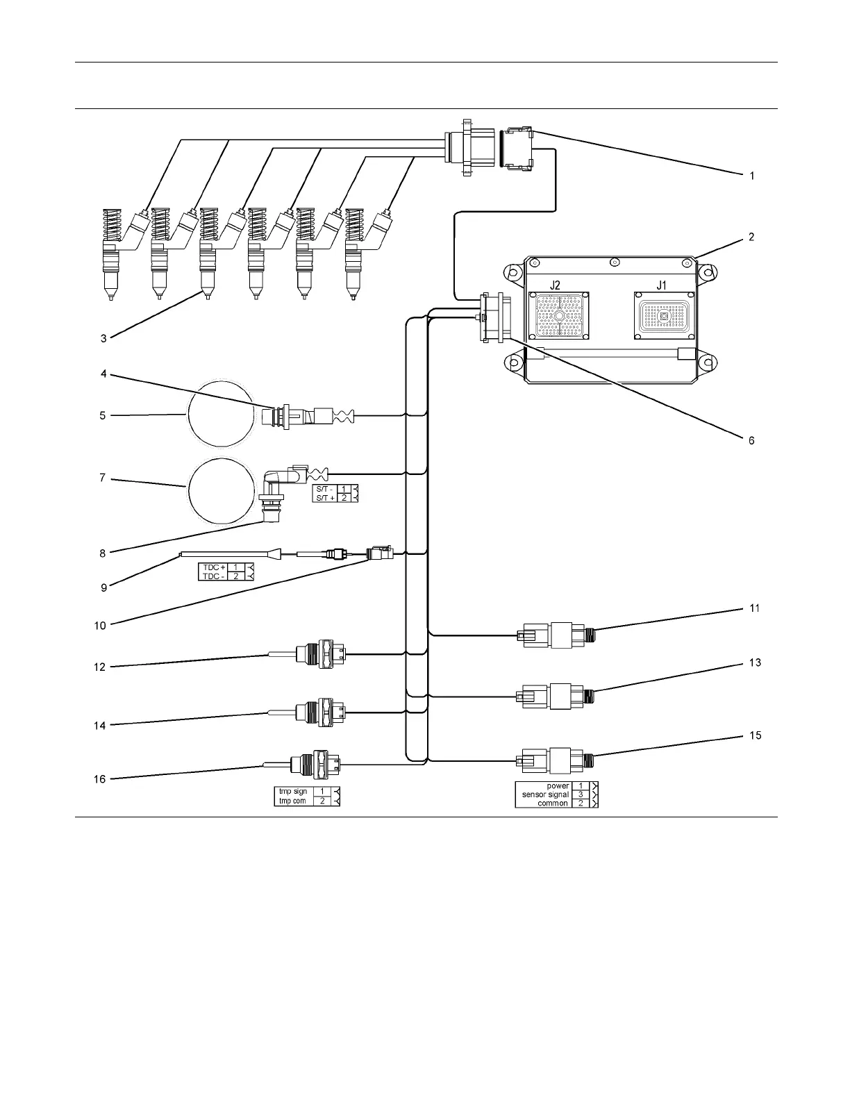
g01407090
Illustration 4
Block diagram for the 2206-13 engine compo nents
(1) 12-Pin Connector
(2) Electronic Control M odule (ECM)
(3) E lectronic unit Injectors
(4) Crankshaft position sensor
(5) 36 - 1 Tooth gear
(6) 120-Pin Conne ctor
(7) 36 + 1 Tooth gear
(8) Cam shaft p osition sensor
(9) Timing calibration probe
(10) Timing calibration probe connector
(11) Atmospheric pressure sensor
(12) Inlet m anifold tem perature sens or
(13) Inlet manifold pressure sensor
(14) Coolant tem perature sensor
(15) Engine o il pressure sensor
(16) Fuel temperature sensor
This document has been printed from SPI². Not for Resale