a. Release hose clamp (10) on plastic tube
assembly (7).
b. Disconnect plastic tube assembly (7) from the
fuel manifold (2).
c. Use Tooling (A) to cap the open port in fuel
manifold (2) with a new cap.
d. Remove seal (11).
e. Use Tooling (A) to plug the open end of plastic
tube assembly (7) with a new plug.
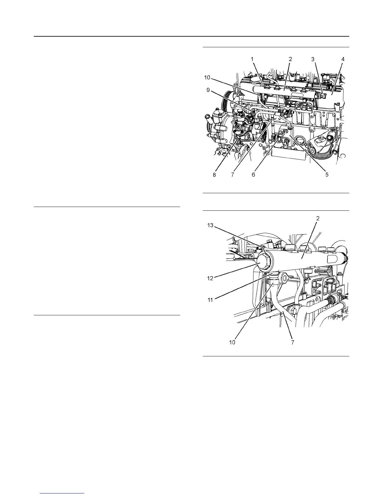
7. If necessary, remove fuel pressure relief valve (12)
and O-ring seal (13) (not shown) from the fuel
manifold.
8. If necessary, remove fuel pressure sensor (3) from
the fuel manifold.
Installation Procedure
NOTICE
Ensure that all adjustments and repairs that are
carried out to the fuel system are performed by
authorized personnel that have the correct
training.
Before beginning ANY work on the fuel system,
refer to Operation and Maintenance Manual, “Gen-
eral Hazard Information and High Pressure Fuel
Lines” for safety information.
Refer to System Operation, Testing and Adjusting,
“Cleanliness of Fuel System Components” for de-
tailed information on the standards of cleanliness
that must be observed during ALL work on the
fuel system.
1. Ensure that all ports on the fuel manifold are
capped. Ensure that the fuel manifold is externally
clean and free from damage.
Note: Do not install a fuel manifold that has not been
plugged. All plugs and caps must be left in place until
the fuel injection lines are about to be installed.
Illustration 17 g03784524
Illustration 18 g03784525
2. If necessary, install fuel pressure relief valve (12)
and new O-ring seal (13) (not shown) to fuel
manifold (2). Tighten fuel pressure relief valve (12)
to a torque of 100 N·m (74 lb ft).
3. If necessary, install fuel pressure sensor (3) to the
fuel manifold. Tighten fuel pressure sensor (3) to a
torque of 70 N·m (52 lb ft).
4. If necessary, follow Step 4.a. through Step 4.d. in
order to install tube assembly (7) to fuel manifold
(2).
a. Position hose clamp (10) onto plastic tube
assembly (7).
16 UENR4503
Disassembly and Assembly Section