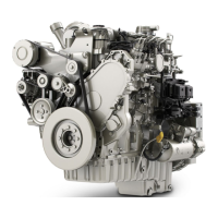
30. Use Tooling (A) in order to cap all open ports
immediately in fuel manifold (24) and in fuel
injection pump (29).
i06213346
Fuel Injection Lines - Install
Installation Procedure
Table 7
Required Tools
Tool Part Number
Part Description
Qty
B
-
LASER 4920
1/2 Inch Drive HP Fuel Line
Socket Set
1
NOTICE
Ensure that all adjustments and repairs that are
carried out to the fuel system are performed by
authorized personnel that have the correct
training.
Before beginning ANY work on the fuel system,
refer to Operation and Maintenance Manual, “Gen-
eral Hazard Information and High Pressure Fuel
Lines” for safety information.
Refer to System Operation, Testing and Adjusting,
“Cleanliness of Fuel System Components” for de-
tailed information on the standards of cleanliness
that must be observed during ALL work on the
fuel system.
Note: The following procedure should be adopted in
order to install the fuel injection lines when the
electronic unit injectors or the fuel manifold have not
been removed. If the electronic unit injectors or the
fuel manifold have been removed, refer to
Disassembly and Assembly, “Electronic Unit Injector -
Install” and Disassembly and Assembly, “Fuel
Manifold - Install” for more information.
Illustration 24 g03829607
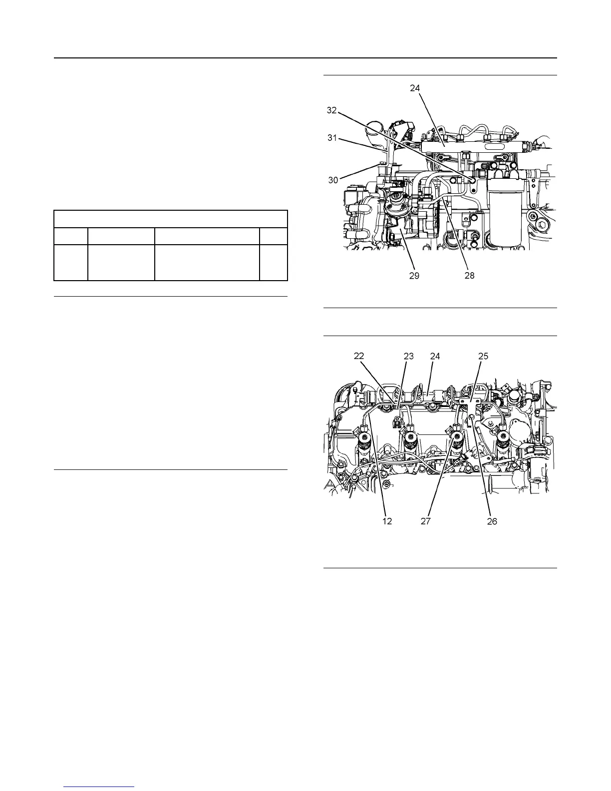
Illustration 25 g03776763
1. Remove the relevant plug from fuel manifold (24)
and fuel injection pump (29).
2. Remove the caps from new fuel injection line (28).
3. Position new fuel injection line (28) onto fuel
injection pump (29) and fuel manifold (24). Loosely
install nuts for the fuel injection line onto the fuel
manifold and the fuel injection pump.
4. Loosely install bolt (32).
5. Use Tooling (B) to tighten the nuts on fuel injection
line (23) to a torque of 25 N·m (221 lb in).
20 UENR4503
Disassembly and Assembly Section