Illustration 28 g02699462
15. Position bracket (19) onto the valve mechanism
cover. Install bolts (20) and tighten the bolts to a
torque of 25 N·m (221 lb in).
16. Install the fuel filter base mounting bracket (21)
(not shown). Refer to Disassembly and Assembly,
“Fuel Filter Base - Remove and Install” for the
correct procedure.
17. Position the wiring harness assembly (11) over
fuel injection lines (12).
18. Install bolt (6) to wiring harness assembly (11).
Tighten the bolt to a torque of 10 N·m (89 lb in)
19. Position wiring harness assembly onto cable
support clamps (1). Secure the clamps and install
to brackets (25).
20. Connect wiring harness assembly (9) to fuel
metering valve (10). Slide the locking tab for wiring
harness assembly (9) into the locked position.
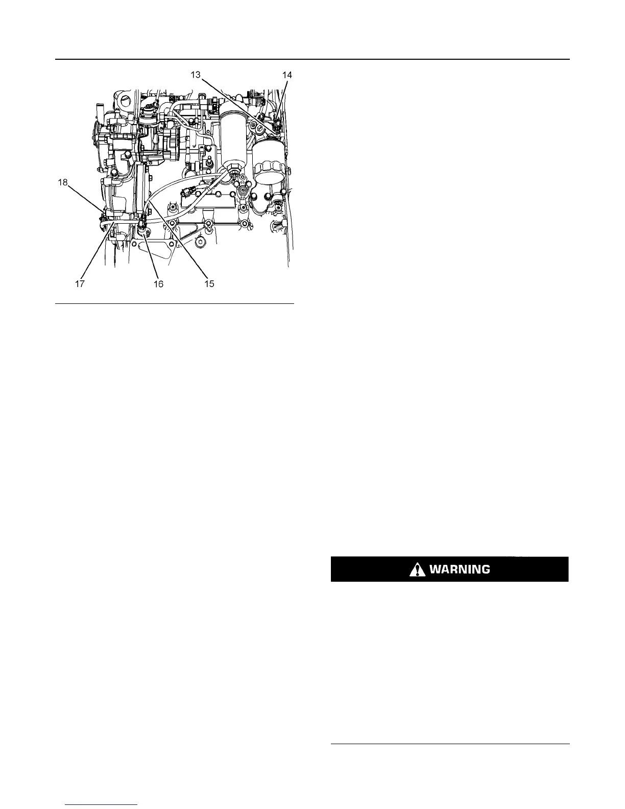
21. Connect wiring harness assembly (14) to oil
pressure switch (13).
22. Connect wiring harness assembly (3) to pressure
sensor (2). Slide the locking tab for wiring harness
assembly (3) into the locked position.
23. Connect wiring harness assembly to fuel
temperature sensor (4). Slide the locking tab for
wiring harness assembly into the locked position.
24. Connect wiring harness assembly (15) to
crankshaft position sensor (16). Slide the locking
tab for wiring harness assembly (15) into the
locked position.
25. Connect wiring harness assembly (17) to
camshaft position sensor (18). Slide the locking tab
for wiring harness assembly (17) into the locked
position.
26. Install cable straps to the wiring harness
assembly in the relevant positions. Ensure that the
cable straps meet the OEM specifications.
27. Install the OEM wiring harness assembly to
connection (5) and connection (8).
28. If necessary, install the Clean Emissions Module
(CEM). Refer to Disassembly and Assembly,
“Clean Emissions Module - Install” for the correct
procedure.
29. Turn the fuel supply to the ON position.
30. Turn the battery disconnect switch to the ON
position.
31. Remove trapped air from the fuel system. Refer to
the Operation and Maintenance Manual, “Fuel
System - Prime” for the correct procedure.
i06211115
Exhaust Cooler (NRS) -
Remove and Install
Removal Procedure
Start By:
a. Drain the coolant from the cooling system into a
suitable container for storage or disposal. Refer to
Operation and Maintenance Manual, “Cooling
System Coolant - Change” for the correct
procedure.
Sulfuric Acid Burn Hazard may cause serious per-
sonal injury or death.
The exhaust gas cooler may contain a small
amount of sulfuric acid. The use of fuel with sulfur
levels greater than 15 ppm may increase the
amount of sulfuric acid formed. The sulfuric acid
may spill from the cooler during service of the en-
gine. The sulfuric acid will burn the eyes, skin and
clothing on contact. Always wear the appropriate
personal protective equipment (PPE) that is noted
on a material safety data sheet (MSDS) for sulfuric
acid. Always follow the directions for first aid that
are noted on a material safety data sheet (MSDS)
for sulfuric acid.
22 UENR4503
Disassembly and Assembly Section